You will get an idea about rtcc panel what is the devices or equipments are used in this panel. This model se avr96 can be fitted into ht panel with minimal wiring scheme.

Download Adt Home Alarm Wiring Diagram
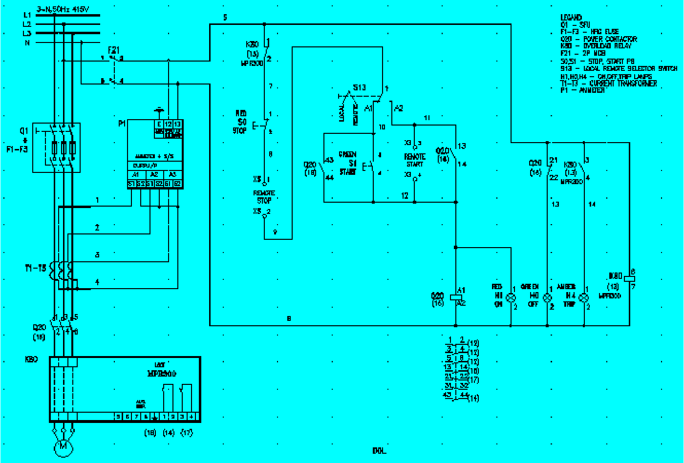
Rtcc panel wiring diagram. Separate rtcc panel not required. 41111 space heater space heater of adequate capacity and robust construction shall be provided inside each control cabi net to prevent moisture condensation. The next step is to get the power from the house battery up to the switch panel where we can use it to do some good. The contacts m will be controlled by the coil mthe output of the motor starter goes to a three phase ac motor. It is used to control the oltc tap changer from the control room or control point itself where rtcc panel is placed. Series parallel wiring thirty two panel solar system 2 groups of 16 watts since we connected thirty two panels together in series and parallel this solar system will output 2016w of power per hour maximum under optimal sunlight conditions.
Space heaters shall be rated for 240 volts 1 phase 50 hz sup ply. Two conductors a positive from the battery switch with a fuse and a negative from the ganged together battery negatives should be ran to where the central switch panel is. Basics 13 valve limit switch legend. General description about rtcc panel for any power or step up transformer. The lower voltage is then used to supply power to the left and right rails of the ladder below. Basics 7 416 kv 3 line diagram.
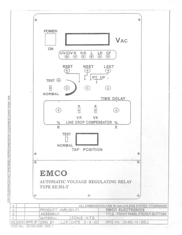
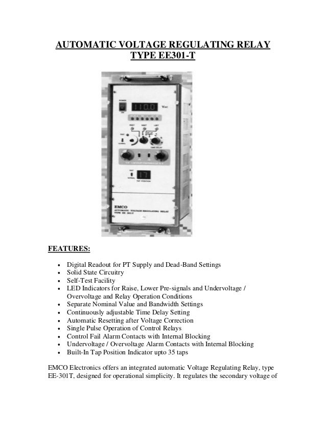
Any difference in two sends a corresponding signal to oltc panel to lower or raise the lv voltage of transformer. System uses an avr avr ma9 to sense the lv voltage and a comparator circuit to compare the sensing voltage with a preset value. Built in voltage control tap measurement and oltc status indications features. Rtcc is installed with transformer ht panel. Basics 10 480 v pump schematic. Draw a circuit diagram connecting transformer oltc rtcc vcb marshalling box otherwise explain in.
Basics 11 mov schematic with block included basics 12 12 208 vac panel diagram. It is used to get the stable output voltage. Solar panel wiring diagram 9usage and limitations. Basics 8 aov elementary block diagram. Basics 14 aov schematic with block included basics 15 wiring or connection. Rtcc panel is called as the remote tap changer circuit.
This is a pretty good amount of power and. 16 x 2pixel line monochrome lcd display the following. Tap change in progress. Answer alleysyed oltc stands for on load tap changer which means that a user. Power is supplied by connecting a step down transformer to the control electronics by connecting to phases l2 and l3. Basics 9 416 kv pump schematic.
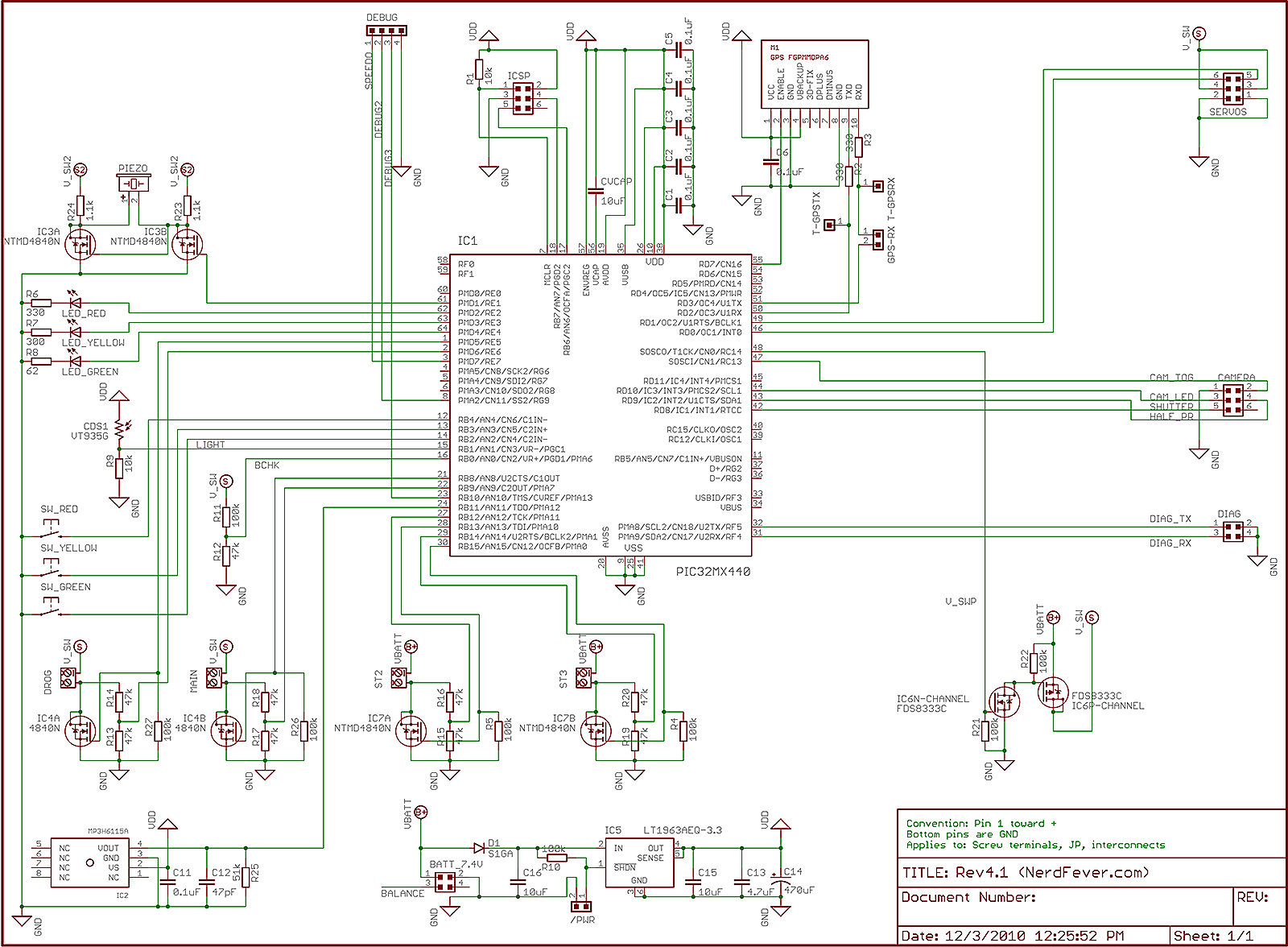
Automatic oltc panel consists of a lcp and a rtcc. Figure 1 a motor controller schematic. Pt under over voltage. Rtcc panel remote. Typical indica tion circuit diagram for rtcc panel is attached as fig.
Gallery of Rtcc Panel Wiring Diagram