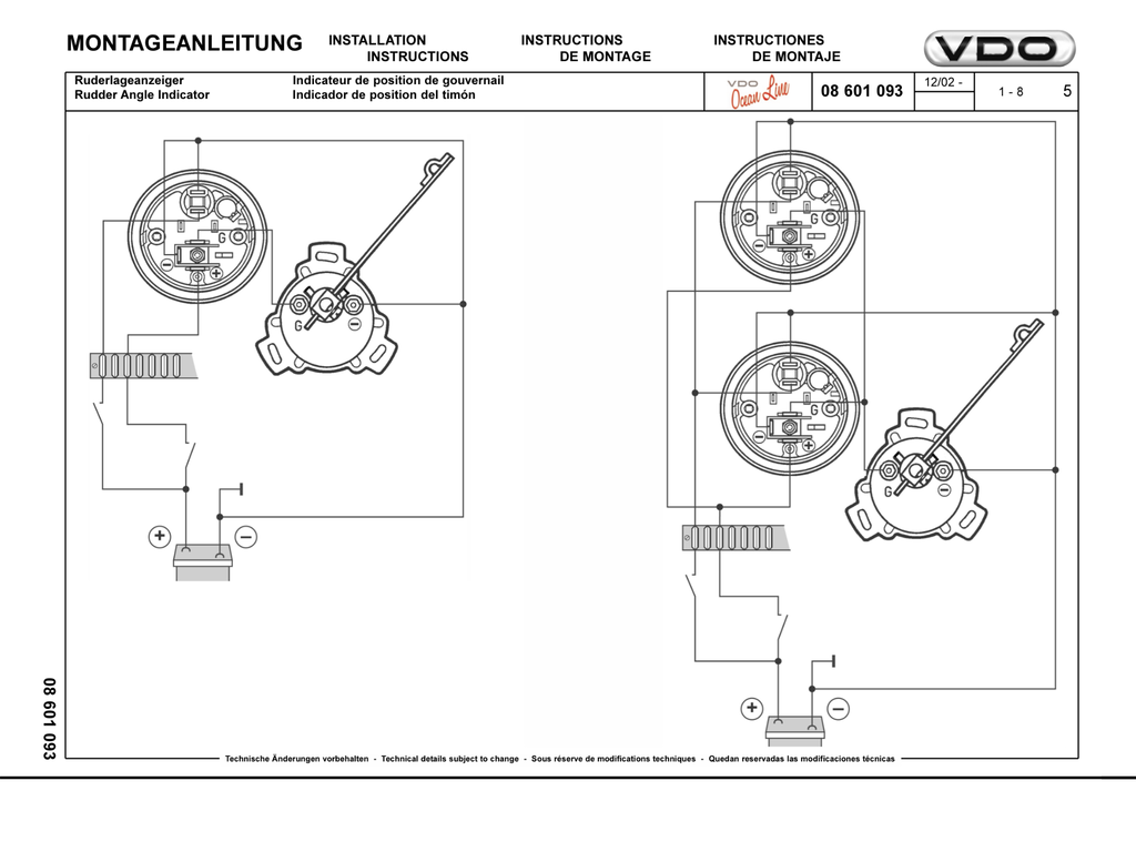
Vdo rudder angle indicator wiring diagram wiring diagram is a simplified adequate pictorial representation of an electrical circuit. Rudder angle indicator automobile electronics pdf manual download.

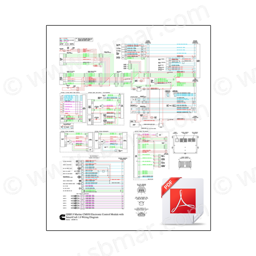
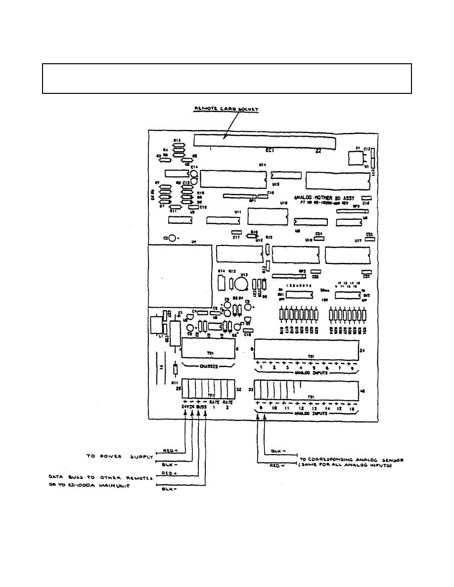
Submarine Electrical Systems Chapter 10
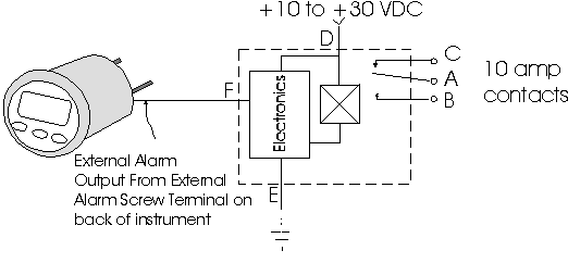
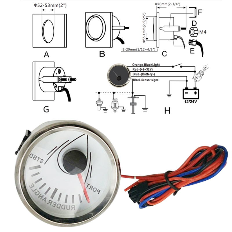
Rudder angle indicator wiring diagram. It shows the components of the circuit as simplified shapes and the aptitude and signal connections in the middle of the devices. The resistor r 05 1k 05w has to be mounted. View and download vdo rudder angle indicator installation instructions manual online. The resistor is not supplied by simrad. This project is quite simple and consists only of a gauge sending unit and interconnect wiring. Rudder angle indicator 52mm 1224v tech support 1 800 265 1818.
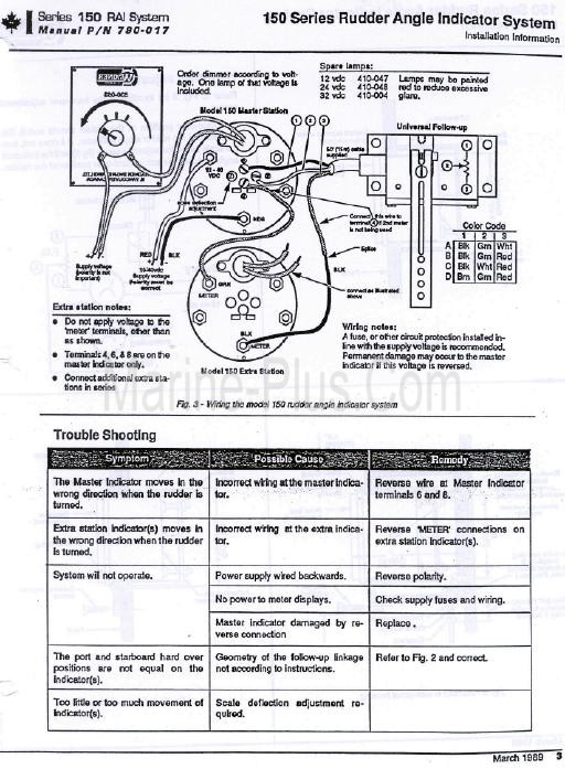
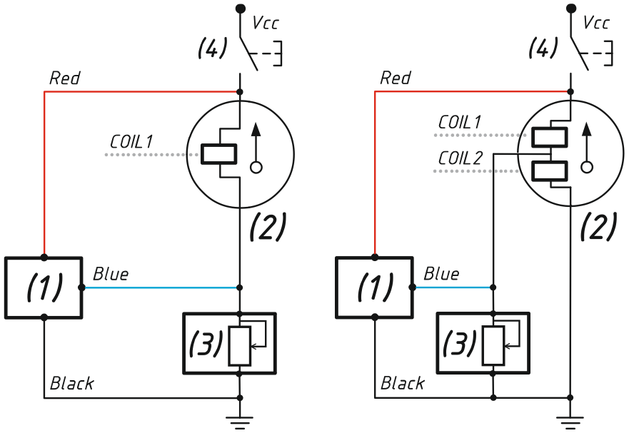
Includes a faria gauge at the helm and a vdo faria rudder position. A the battery switched power after the fuse box or. Wiring to the ri9 and the panorama mk2 rudder angle indicators is shown in figure 2 4. See page 3 for mounting options and instructions wiring the gauge illustration a. The above connection diagram shows how to connect an ri9 rudder angle indicator to an ap50 system with rf14xu rudder feedback unit. The ri9 rudder angle indicator is connected to the u terminal on rf14xu.
From assembly or wiring diagram. This configuration is for 24vdc only. Always disconnect battery ground before making any. The cables are carried through cable glands and connected to the terminal board. Route wires from the instrument to. 26122018 26122018 0 comments on vdo rudder angle indicator wiring diagram what is needed then is a rudder indicator to aid in centering the rudders prior to shift steering.
Figure 2 5 and figure 2 6 also show how a combination of ri9 and panorama mk2 can be connected to the rf14xu.
Gallery of Rudder Angle Indicator Wiring Diagram