If you have any questions or doubt about how to use install or wire any battery switch consult a certified marine. Wiring diagrams do not show the.

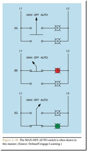
Hand Off Automatic Controls Basic Control Circuits
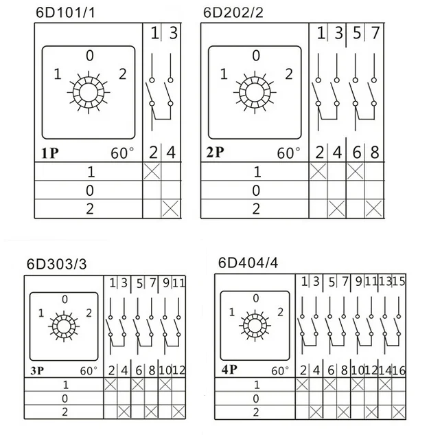
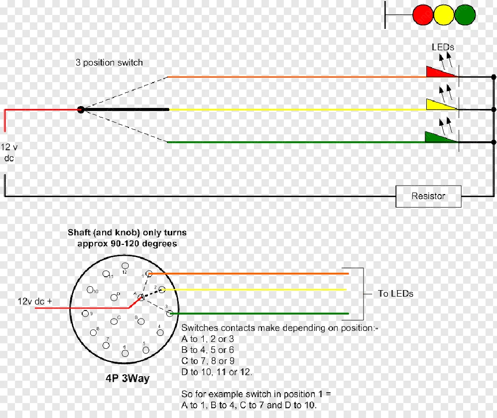
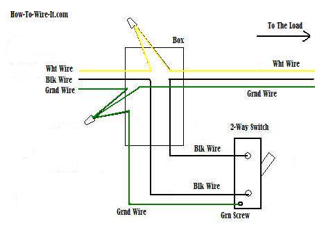
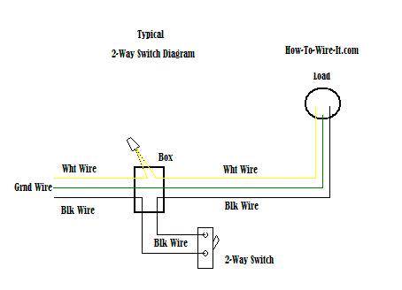
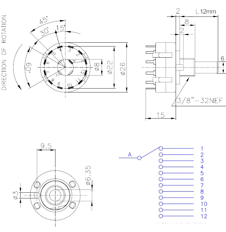
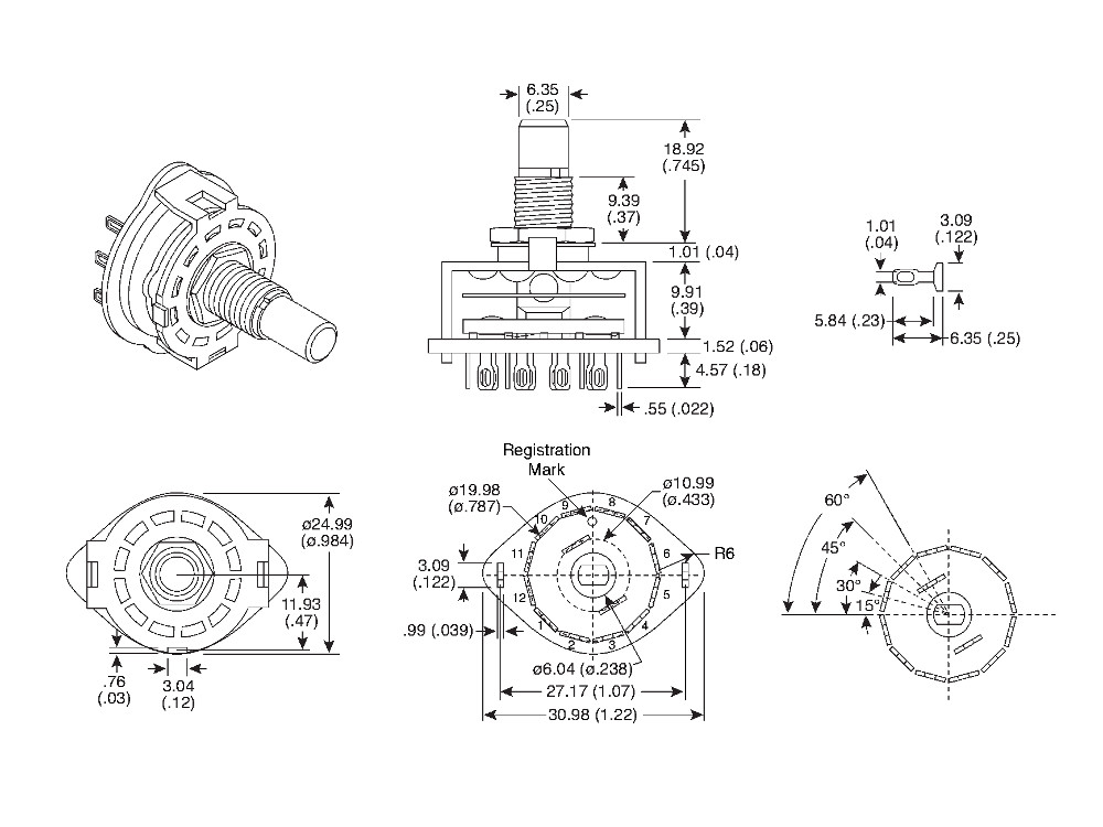
Selector switch 2 position wiring diagram. Lever mounted on the front of the switch. Learn how this truth table illustrates the manual or automatic contact positions of two contact selector switch. 2 position selector switch 3 position selector switch 2 position selector push button no. But adding on off switches to the circuit you can force the alternator to charge the battery you want charged. Illuminated 1 7 2 and 3 position dimensional drawings 1 8 wiring diagrams 1 8 installation instructions 1 8 selector switches. I 2 bo 0 ed a x b x f c r anti plugging heavy duty selector 3 position 1 2 3 s 0 fid swtwt.
Wiring diagram book a1 15 b1 b2 16 18 b3 a2 b1 b3 15 supply voltage 16 18 l m h 2 levels b2 l1 f u 1 460 v f u 2 l2 l3 gnd h1 h3 h2 h4 f u 3 x1a f u 4 f u 5 x2a r power on optional x1 x2115 v. Ammeter selector switch with centre off 3. Ammeter switches with 0 position start selector switches. 2 position 1 9 illuminated non illuminated keyed dimensional drawings 1 10 installation instructions 1 10 selector switches. Double circuit mushroom head wobble. Pole change switches and reversing pole change switches page 363.
Switching diagrams and further switching programmes page detailed. Contact position on a selector switch can easily be illustrated using truth tables. Running with a selector switch in the both position see selector switches may not fully charge all batteries. Wiring diagrams 1 6 installation instructions 1 6 push pull operators. Selector switch jo jo 2 position 3 position heavy duty selector 2 position 1 2 letter posltlon al sm. Rotary cam switches from salzer are manually operated independently programmable.
Gallery of Selector Switch 2 Position Wiring Diagram