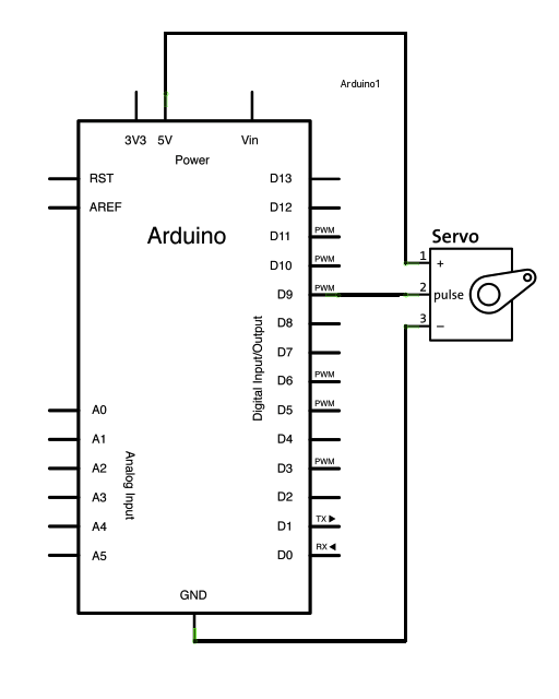
Servo motor resolver wiring. Arduino to servo motor wiring diagram.
Servo Motor Control With An Arduino Projects
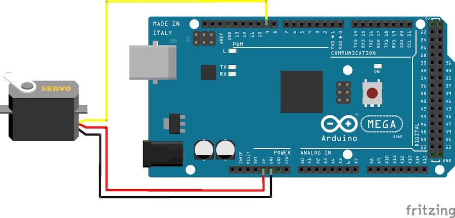
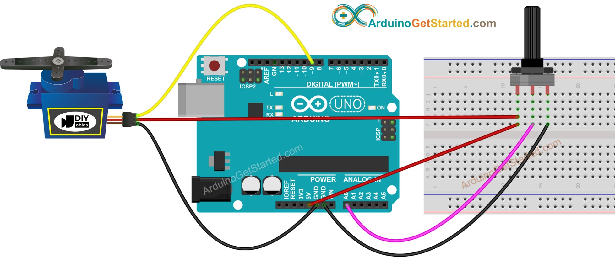
Servo motor wiring diagram. June 4 2019 by larry a. Wiring diagram the best thing about a servo motor is that it can be connected directly to an arduino. It shows the components of the circuit as streamlined forms and the power and signal connections in between the devices. Since it only happens 30 times a second thats the minimum reaction time. These colors are as. This is called the neutral position.
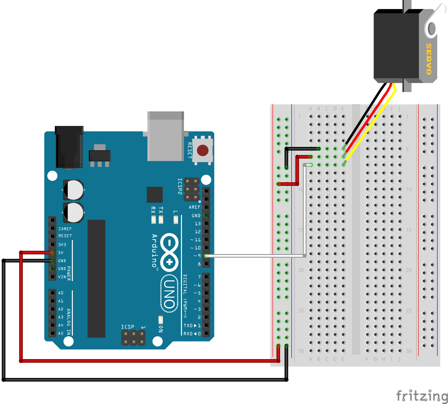
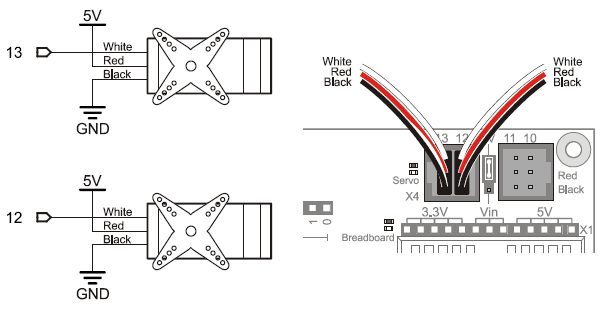
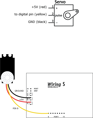
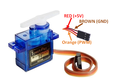
The motor of an analog servo receives a signal from the servo amplifier inside the servo at 30 times a second. Since it only happens 30 times a second thats the minimum reaction time. Connect to the motor to the arduino as shown in the table below. Servo motors are widely used in different types of applications and suitable for movement or rotation based mechatronic needs. Servo motor is a component that can rotate its handle usually between 0 and 180. Vcc pin typically red needs to be connected to vcc 5v gnd pin typically black or brown needs to be connected to.
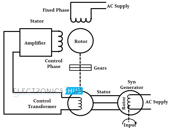
If you ever plan to replace or test a resolver then you need to know the functions of each wire. This pulsing signal tells the servo motor when to start rotating and which way to rotate. A wiring diagram is a simplified conventional pictorial depiction of an electric circuit. Mg996r servo motor wiring diagram click the image to enlarge it the mg996r is a metal gear servo motor with a maximum stall torque of 11 kgcm. The servo motor used in this example includes three pins. Servo red wire 5v pin arduino.
Servo motors that dont produce high torque typically contain plastic gears. The length of the pulse will determine how far the motor turns. Wellborn variety of servo motor wiring diagram. The servo typically requires pulse every 20 milliseconds 02 seconds. The motor of an analog servo receives a signal from the servo amplifier inside the servo at 30 times a second. A better look at the circuit board dc motor and potentiometer.
If the pulse is shorter than 15 ms the motor will turn the shaft to close to 0 degrees. Every servo motors will have three terminals one for positive supply another for ground supply and other one for position control signal input. Most servo motors run on 5v so you can attach the red lead to the arduinos 5v pin. Generally 15 millisecond pulse will make the motor turn to the 90 degree position. Like other rc servos the motor rotates from 0 to 180 degree based on the duty cycle of the pwm wave supplied to its signal pin. There is an industry standard for resolver wire colors that most manufacturers choose to use.
This pulsing signal tells the servo motor when to start rotating and which way to rotate. It used to control the angular position of the object. To begin wire this circuit. This can be very difficult to determine with out a little knowledge and a voltmeter.
Gallery of Servo Motor Wiring Diagram


.png)