232 basic functions in contrast to other disc brakes with a dc coil the sew brakes operate with a two coil system. Product training 23 troubleshooting.
6865 North Star 165603m Wiring Diagrams Wiring Library
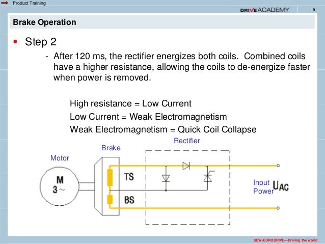
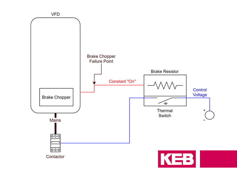
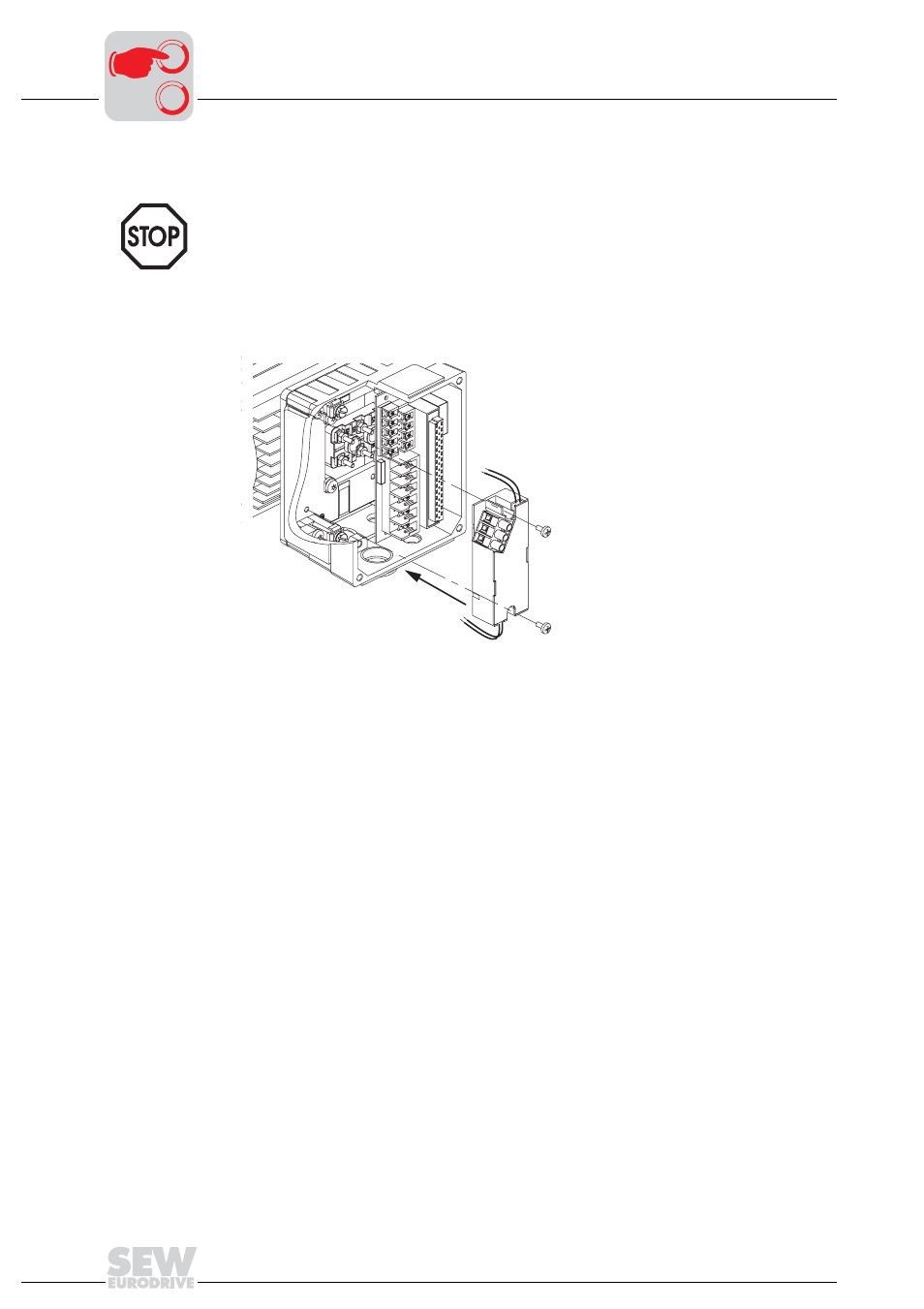
Sew brake rectifier wiring diagram. Product training 8 brake operation. The bme brake rectifier is a half wave rectifier with overvoltage protection elements and electronic control for reducing the brake release reaction times. It functions like the rectifier type bge however it is designed to be mounted in a control panel on din rail and not in the motors conduit box. The brake will release and allow the motor to rotate when the nameplate ac brake voltage v b is supplied to the brake rectifier terminals. The wiring diagrams for brake connections are located on the inside of the motor conduit box lid. In addition they may be wired for either normal or rapid stopping.
When connecting the supply power from the motor terminal block to the brake rectifier follow the specifications below. The integrated design of the sew brake motor makes for particularly compact and sturdy solutions. An sew brake rectifier controls both coils. 6 2018 common connection diagrams 24 brake control sew brakes are available for either normal or rapid starting. 241 normal starting bg the bg rectifier provides normal starting which is sufficient for most applications with low or infrequent cycling. Connecting wire is to be awg14 mtw 600v 105c temperature rating and black col or.
Fractional accelerator sew eurodrivedriving the world brake coil. A characteristic feature of sew brakes is th eir very short length. The recommended ring terminals are manufactured by thomas betts or equivalent. There are certain cases where the brake rectifier can receive its voltage from the motors. Refer to the operating instructions for wiringrefer to the operating instructions for wiring diagrams sew eurodrivedriving the world. The brake endshield is a part of both the motor and the brake.
Gallery of Sew Brake Rectifier Wiring Diagram