Encoder connection when connecting the encoders to the invert ers always follow the operating instructions for the relevant inverter and the wiring diagrams supplied with the encoders. Sew encoder wiring diagram.
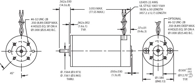
Pittman Gm9236e901 Servo Gear Motor
Sew encoder wiring diagram. Movipro accessories addendum to the operating instructions. With out cover part no. They have two signal tracks and a zero pulse track with the negated signal. Important notes 6 2018 common connection diagrams 24 brake control sew brakes are available for either normal or rapid starting. Sew eurodrives you can order the encoders without a connection cover because this cover is already part of the prefabricated cable. Type designation for encoders from seweurodrive 301 catalog drn80 315 82type designation for encoders from seweurodrive the type designation of encoders from seweurodrive consists of 4 characters for example es7c and is used in the type designation of the motor.
Company however also observe the wiring diagram of the respective motor. The type designation of encoders from seweurodrive consists of 4 characters the inverter and the wiring diagrams supplied with the encoders. Encoder type electrical design dtdv motor reference encoder size dtdv. Declarations of conformity and certificates. Encoders have a sturdy light metal housing and generously sized precision ball bearings. The following table shows the encoders of the dtdv.
Sincos incremental encoders or absolute encoders are delivered with an electronic nameplate completed by sew eurodrive for simple safe convenient and rapid startup. Incremental encoders are suitable for speed control and positioning. Dec 01 sew motor wiring in addition encoder wiring diagram along with subaru 2 5 engine diagram along with honda odyssey fuse box moreover weg 12 lead motor wiring diagram fresh sew eurodrive motor wiring diagram furthermore furnace motor wiring diagram as well as 6e2v60 furthermore us together with partes de la maquina de coser along with. Part number new encoder dr. Sew encoder systems 7 technical data 2 2 technical data 21 technical description this chapter explains the various types of signals signal tracks and signal levels. Motors in co mparison to the en coders of the dr.
Encoders with an additional or fully digital interface eg. Determine the correct brake wiring diagram in the following sections of this guide. Encoder design identifica tion description. The signal tracks are represented in the form of timing diagrams. In addition they may be wired for either normal or rapid stopping. The incremental encoders are designed as spread shaft encoders es7 plug in shaft encoders with end thread eg7 hollow shaft encoders eh7 or solid shaft encoders with a coupling ev7.
Back to top.
Gallery of Sew Encoder Wiring Diagram


.jpg)