See how the anti. A wiring diagram usually gives information about the relative position and arrangement of devices and terminals on the devices to help in building or servicing the device.
Wire Diagram
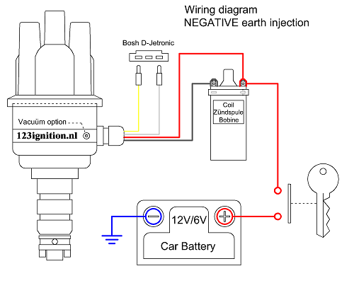
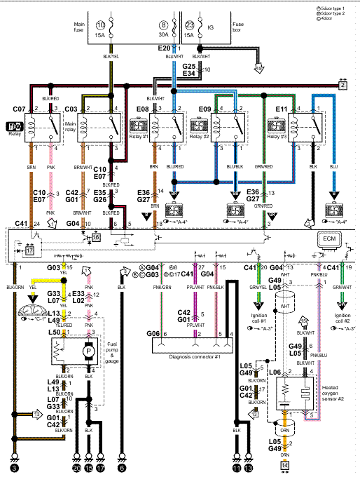
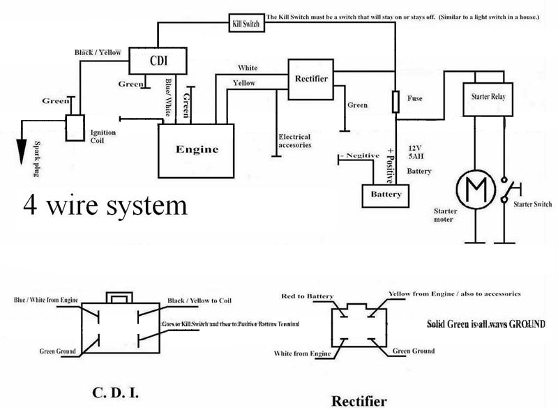
Show me the wiring diagram. The diagram is surrounded by a alphanumeric loaction grid. The ignition key supplies the power to actuate a relay which in turn actuates the solenoid. This is unlike a schematic diagram where the arrangement of the components interconnections on the diagram us. A chevy starter requires a lot of amperage which in turn requires a large 4 gauge wire from the battery to the starter solenoid. It shows the components of the circuit as simplified shapes and the power and signal connections between the devices. Wiring diagrams description these diagrams use a new format.
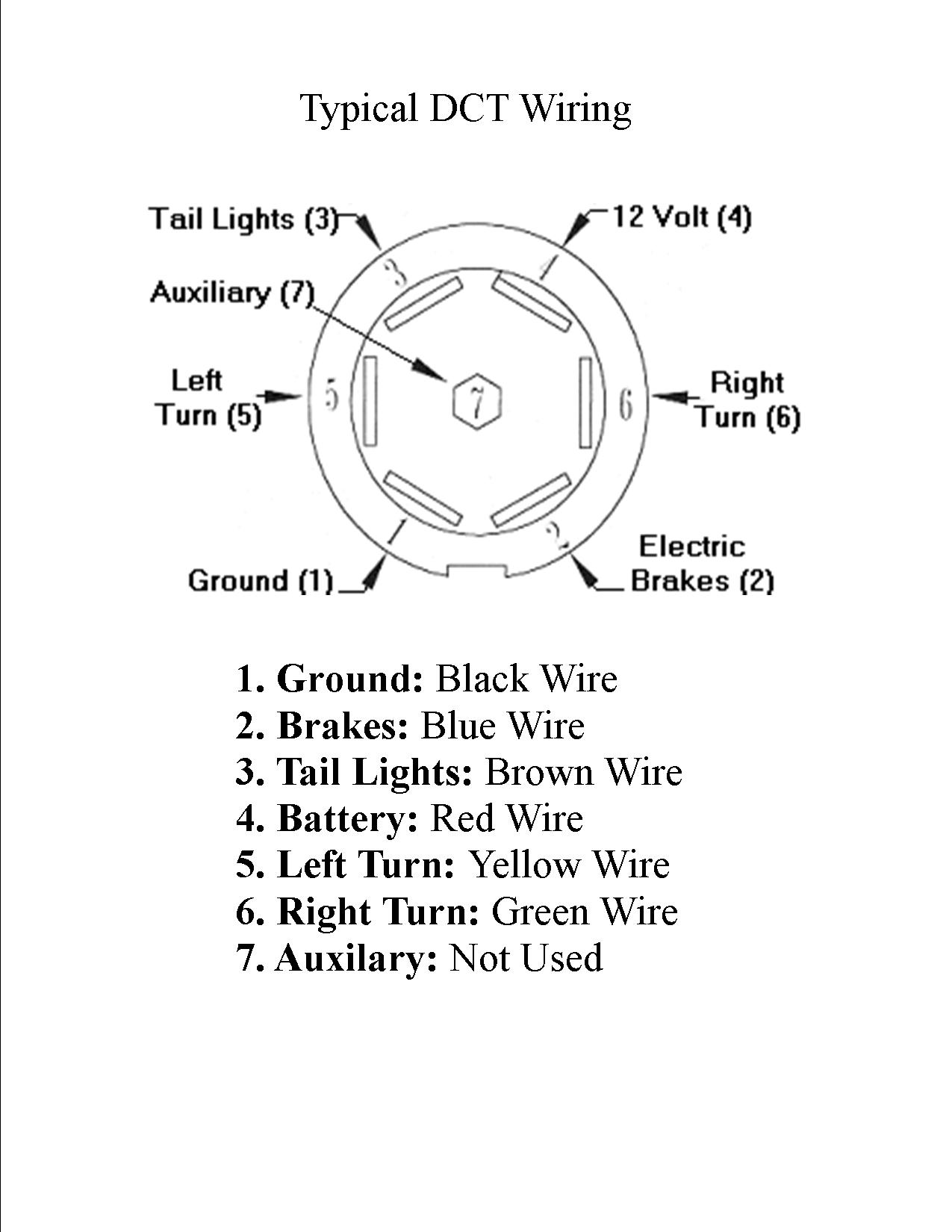
The connectors are shown with end on views with. The solenoid acts like a switch opening and closing the high amperage circuit to the starter. Wiring a 20 amp 240 volt appliance receptacle. Single pole may sound simple but there are different ways to wire a single pole switch. All the wires at the connectors have alphanumeric addresses showing where the other end of the wire is located ac cording to the grid. The neutral from the source is spliced through to the switch box using the white wire and in this diagram the white wire is capped with a wire nut.
A wiring diagram generally provides details about the relative position and plan of gadgets and also terminals on the gadgets in order to help in building or servicing the device. This represents a change in the nec code that. This outlet is commonly used for a heavy load such as a large air conditioner. A wiring diagram is a simplified conventional pictorial representation of an electrical circuit. The power can come from either the switch box or the fixture box and a set of electrical switch wiring diagrams will explain each of these scenarios to you clearly. A wiring diagram is a streamlined standard pictorial depiction of an electric circuit.
Wiring color codes here is a listing of common color codes for evinrude and johnson outboard motors. Most models also have black white only. Switch wiring diagrams a single switch provides switching from one location only. Learn to navigate this systems wiring circuitry and diagram using current flow analysis relay and module operation and neutral switch actuation such as circuit completion. It shows the elements of the circuit as simplified shapes and also the power as well as signal links in between the gadgets. The linked images are printable but may print across more than 1 page in order to be legible.
With this wiring both the black and white wires are used to carry 120 volts each and the white wire is wrapped with electrical tape to label it hot. The outlet should be wired to a dedicated 20 amp240 volt circuit breaker in the service panel using 122 awg cable. These codes apply to later model motors approximately early 80s to present. In this updated diagram 3 wire cable runs between the receptacle and switch and the red cable wire is used to carry the hot source to the switch.
Gallery of Show Me The Wiring Diagram