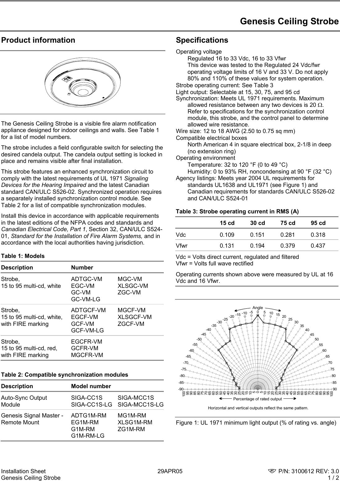
It reveals the parts of the circuit as streamlined forms and also the power as well as signal connections between the tools. Genesis signal master remote mount adtg1m rm mg1m rm eg1m rm xlsg1m rm g1m rm zg1m rm.

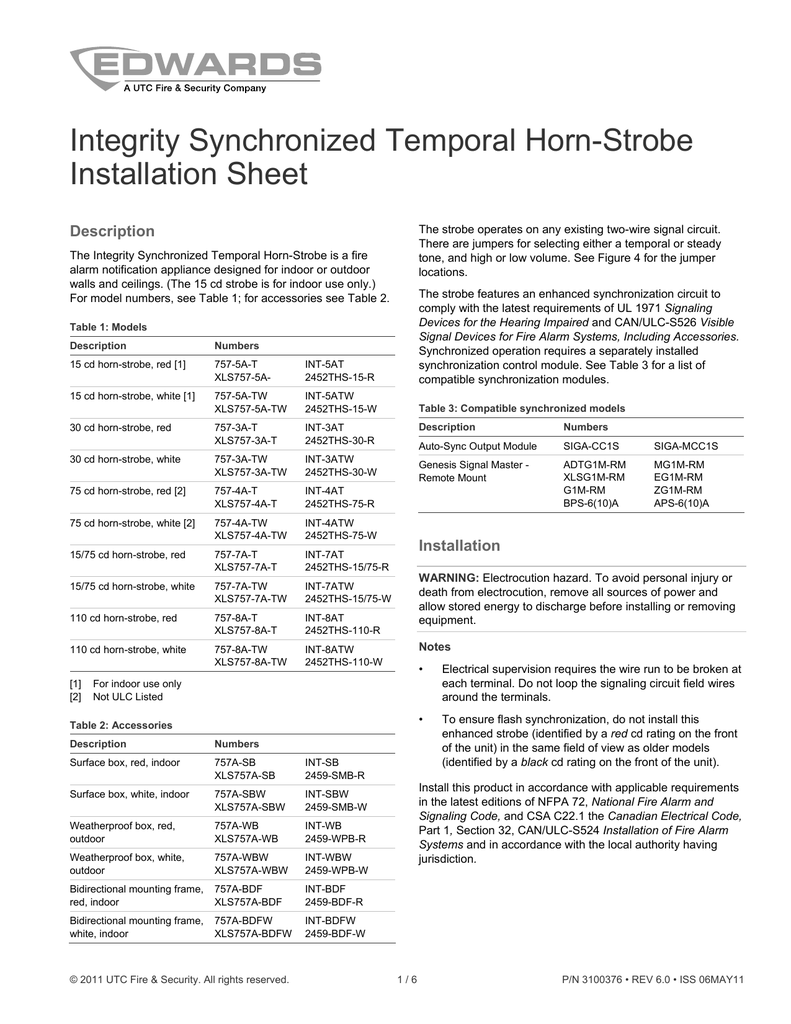
Data Sheet 85001 0543 Synchronization Output Module
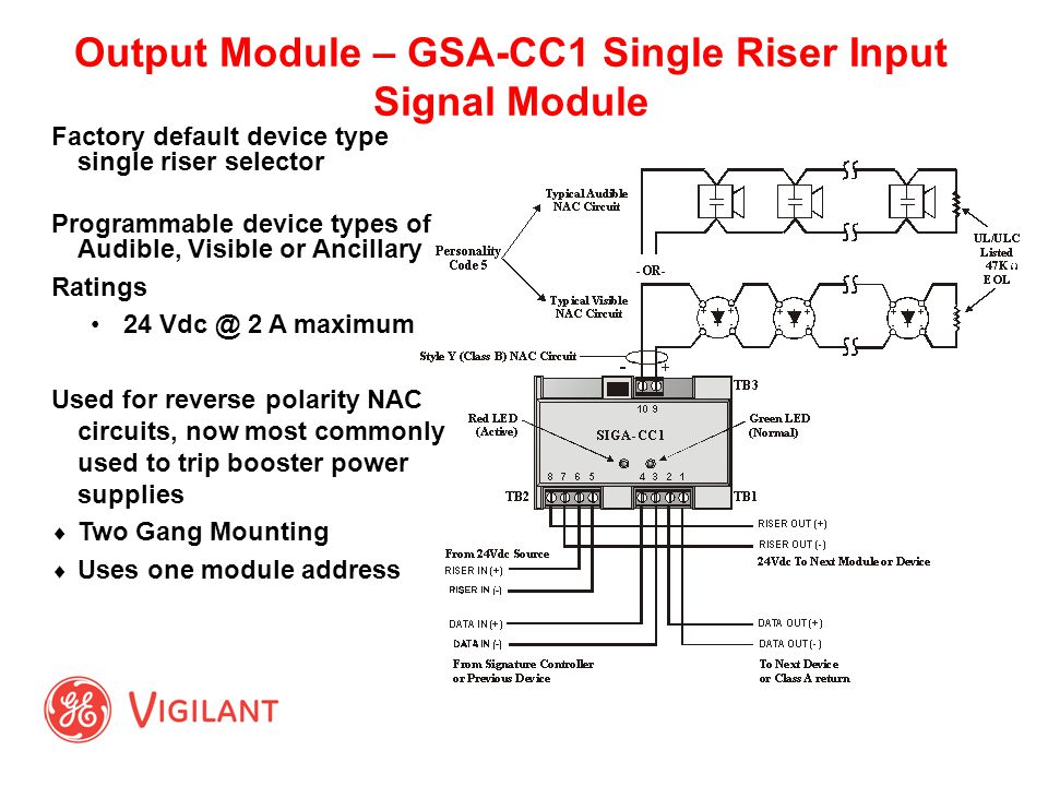
Siga cc1s wiring diagram. Siga cc1s synchronization output modules are intelligent analog addressable devices that form part of ge securitys signature line of products. Provides the installation procedures wiring diagrams dip switch settings etc. The fire alarm control panel provides this function. About 6 mm from the ends of all wires that. A wiring diagram is a schematic which uses abstract pictorial symbols to demonstrate each of the interconnections of components in a very system. Siga cc1s wiring diagram whats wiring diagram.
Cc1s wiring diagram telephone is off hook and when the circuit is shorted which causes a trouble figure 3. An initial take a look at a circuit diagram could be complex yet if you can read. Siga cc1s genesis g1m rm fireshield panel or a bps generating genesis. 3 position rotary switch schematic. To wire the module. Receiving from point a to aim b.
Damper end switch wiring diagram. Siga cc1s wiring diagram a novice s guide to circuit diagrams an initial take a look at a circuit diagram could be complex yet if you can read a metro map you could review schematics. Uioxr motherboard terminals are suited for 12 to 18 awg 25 mm 2 to 075 mm. Collection of siga cc1s wiring diagram. Before replacing a siga cc1 module tag the wires to ensure correct reconnection. Wiring diagram for nac personality code 5.
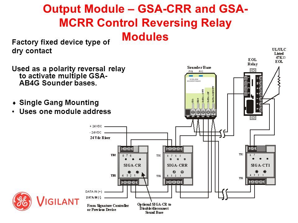
The actual operation of the siga cc1s and mcc1s is determined by the personality code selected by the installer which is downloaded to the module from the signature loop controller during. 1 signal polarity is. Siga cc1s wiring diagram a novice s guide to circuit diagrams. A wiring diagram is a streamlined conventional pictorial representation of an electric circuit. Literally a circuit is the path that enables power to circulation. Auto sync output module siga cc1s siga mcc1s gsa cc1s gsa mcc1s.
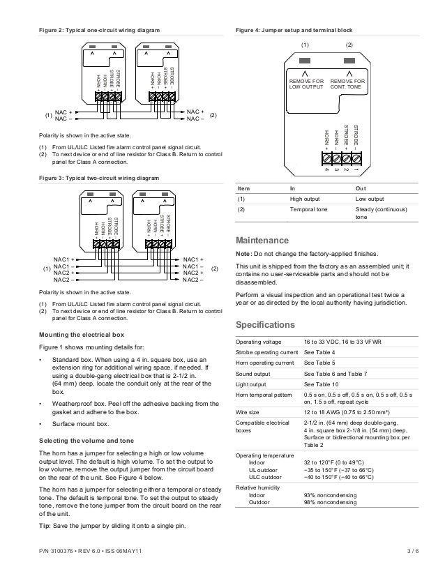
Do trailer lights need to be grounded. Dryer machine plug adapter. Typical wiring siga cc1s standard mount siga mcc1s uio mount 10 9 8 7 6 5 4 3 2 1 tb1 cc1s to next device or eol resistor. Siga cc1s wiring diagram a novice s guide to circuit diagrams. Verify that all field wiring is free of opens shorts and ground faults. The siga cc1 module does not supervise the riser.
To reduce the risk of shock disconnect all power and allow 10 minutes for stored energy to dissipate before handling. Siga cc1s and mcc1s synchronization output modules are intel. How to wire a coil.
Gallery of Siga Cc1s Wiring Diagram