Series d m9n d m9p d m9b 1 wiring should be kept as short as possible. Validated d m9 components according to iso 13849.

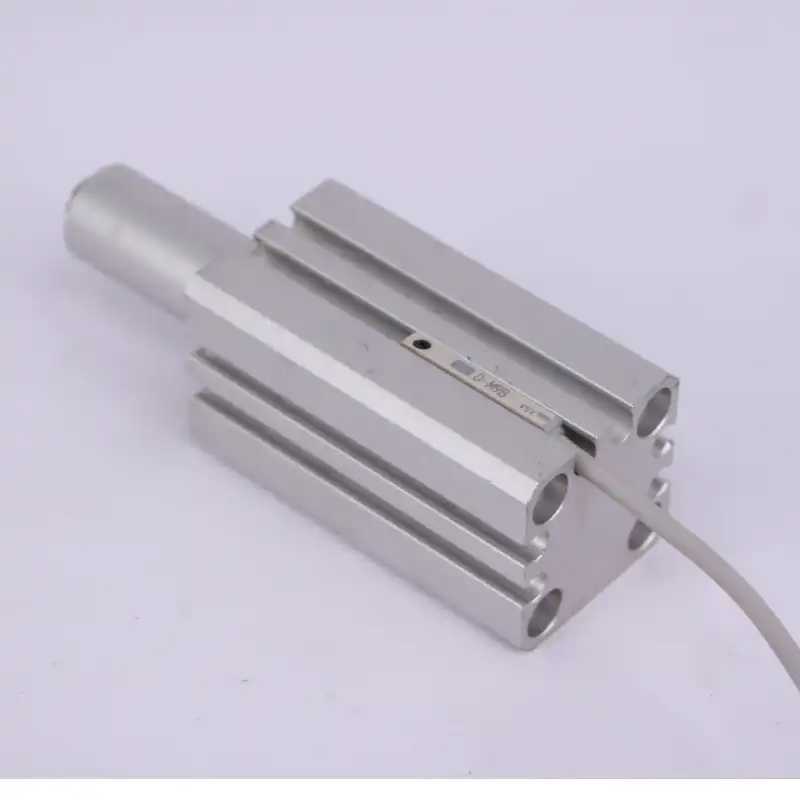
10pcs Lot Solid State Auto Switch Direct Mounting Type D M9b D M9n D M9p D M9bl D M9nl D M9pl Magnetic Senson For Air Cylinder
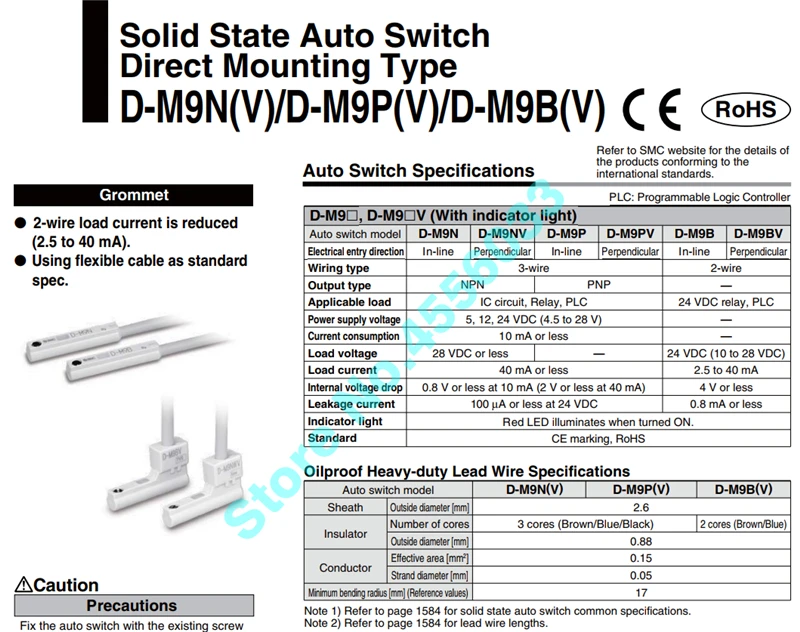
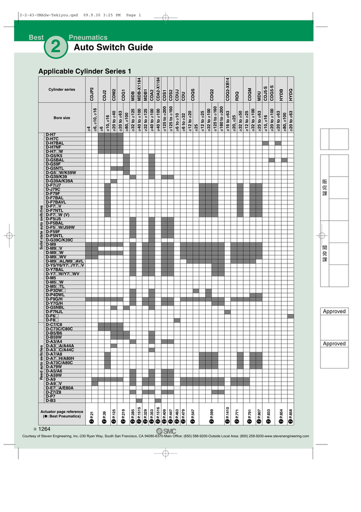
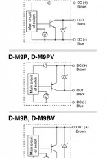
Smc d m9n wiring diagram. Auto switch operating range mm do not use a cable longer than 100 m. D m9n d m9p d m9b 7 13 38 63 g lead wire length grommet note 1 refer to page 1194 for solid state auto switch common specifications. Page 1 4 be sure to confirm the load condition eg. Dimensions d m9 2 wire load current is reduced 25 to 40 ma. Xlthe conventional model smc xlq d xvd xgt cyv xm xy solid state auto switch direct mounting style d m9nd m9pd m9b auto switch internal circuit d m9n d m9b d m9p auto switch specifications mass auto switch model 05 1 3 5 d m9n 8 14 41 68 d m9p 8 14 41 68 d m9b 7 13 38 63 g lead wire length m grommet plc. Operation manual manual installation and maintenance manual.
Smc networks d m9n operation manual 28 pages. Smc networks d m9n manuals manuals and user guides for smc networks d m9n. Smc d m9n smc d m9n npn 3 wire pneumatic auto switch app. Page 2 the number shown in brackets indicates the connector pin number. 1 wiring should be kept as short as possible. Current 28v dc max.
The intended use of this product is to detect a position of a magnet in a pneumatic cylinder. Connection and current caution the maximum piston speed is. Complies with the basic safety principles in accordance with iso 13849 load operating time ms explosion may result. Series d m9n d m9p d m9b value before power is supplied. Programmable logic controller. We have 3 smc networks d m9n manuals available for free pdf download.
Ic circuit plc relay 40ma max. Flexibility is 15 times greater than the conventional model smc comparison. Note 2 refer to page 1194 for lead wire lengths.
Gallery of Smc D M9n Wiring Diagram