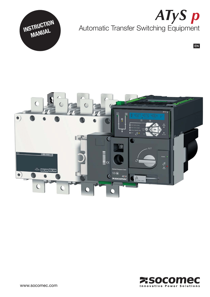
They incorporate all the functions offered by the atys d as well as functions intended for mainsmains applications atys t and mainsgenset applications atys g. General safety instructions this manual provides instructions on safety connections and operation of the atys s and atys sd motorised changeover switches manufactured by socomec.

Read Or Download 92 S10 Fuel Pump Wiring Diagram For Free At
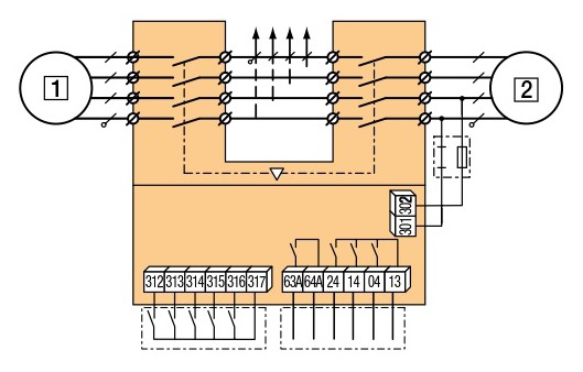
Socomec atys r wiring diagram. Sensing kit wiring diagram. Step 1 cabinet back. Control relay atys c30 d10 or d20. The atys family product range. Atys r 4f rtse en 3. Atys s sd r d t g p.
S1 kva sg kva comut 044 a t1 ncl q1 cl q2 ats g comut. Socomec atys 3s wiring diagram transfer switching technology by socomec atys 125 3200a youtube socomec atys 3s wiring diagram wiring diagram is a simplified okay pictorial representation of an electrical circuit. Control relay atys c40. They enable the on load transfer of two three phase power supplies via remote volt free contacts from either an external automatic controller using pulse logic or a switch. 4 technical information standard diagrams transfer between 2 sources 2 bus bars first type of architecture. Recommanded to use socomec voltage sensing kit refer to atys g accessories for details step 4 541 996 c 0214 en clip for storage of the.
Atys r and atys d are 3 or 4 pole remotely operated motorised transfer switches with positive break indication. Wiring and if ok power up the product. Atys m modular transfer switching equipment from 40a to 160a motorised and automatic change over switches 125a to 3200a atys d m atys g m atys p m atys r atys g atys p. On led manueldefaut red ensure that the emergency handle is not inserted in the product and turn. The following diagrams offer technical solutions based on socomec transfer switches in order to meet most of the ats installation diagrams made with others technologies. For further details please refer to the instruction manual in chapter spare parts and accessories 541 991 f 1016 en quick start atys r motorised source changeover switch en control command terminals ensure that the product is in manual mode.
Sensing kit wiring diagram standard43 744. Atys t and atys g are 3 or 4 pole automatic transfer switches with positive break indication. 541 892 c 1. It shows the components of the circuit as simplified shapes and the capability and signal friends between the devices. Motorised switch cl ncl g q1 q2 ats automatic transfer switch protection arent shown on the following schemes. 4 atys s sd réf.
Atys 836 a atys 599 c socomec products.
Gallery of Socomec Atys R Wiring Diagram