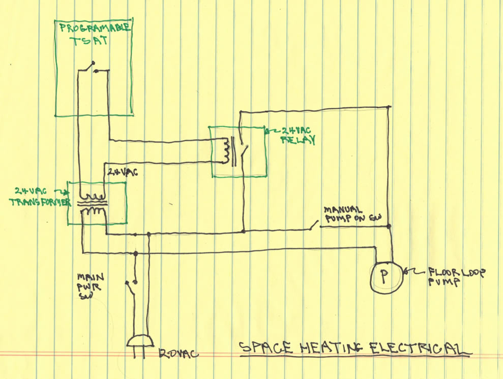
Any load above 15 amps needs to be split up and use a sunstat relay or an additional thermostat to carry part of the system. Using an additional thermostat will require another floor sensor for it to work with.

Floor Heat Floor Heat Wiring Diagram
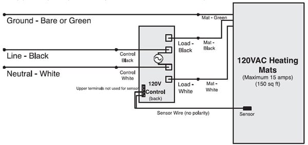
Suntouch thermostat wiring diagram. Line side wires connect to incoming power from the breaker panel and load side wires connect to the floor warming system power leads. Representative heat area for maximum system perfomance. The probe wire cannot cross any heater wires and the temperature. Floor sensing thermostat programmable or non programmable. Sensor must not be directly or adjacent to a heating wire. If your multi meter detects line voltage on the load side wires of the control when it is turned off or in stand by the control will have to be replaced.
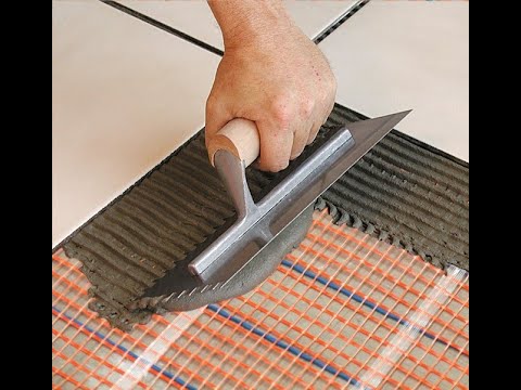
Suntouch mat is a complete heating mat consisting of a series heating wire and a power lead for connection to the electric power supply. Sensing probe should be centered between the wires in the mat. Verify each of the wire connections is correct per the diagram on the back and you have 4 wire nut connections to the control and a 5th wire nut connection for the ground wires. Return control to dealer for replacement. Consult the wiring diagram on the back of the control the instructions that came with the control or the wiring diagram in this manual. The sensing probe should be placed in a.
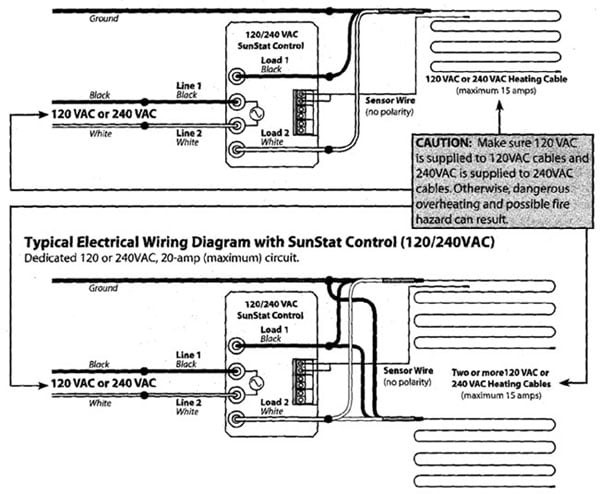
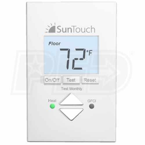
Each suntouch sunstat control is rated for 15 amps maximum whether 120v or 240v. The heating wire length cannot be cut to fit. You can see the full list we carry here. Suntouch mats must be controlled by a sunstat floor sensing thermostat. Test the amp load on the control. Yes you can actually replace any older suntouch thermostat with any of the current suntouch models.
Refer to the wiring diagram on the back of the control. 120 vac 240 vac 1 phase see table 2 watts. 12 wsqft 41 btuhsqft.
Gallery of Suntouch Thermostat Wiring Diagram
%2C445%2C291%2C400%2C400%2Carial%2C12%2C4%2C0%2C0%2C5_SCLZZZZZZZ_.jpg)