Thermostat wiring diagrams for heat pumps heat pump thermostat wire diagrams. July 25 2018 by faceitsalon.
Fast Stat 1000 And Common Maker Installation Guide Simple
Thermostat 4 wire wiring diagram. A wiring diagram is a streamlined conventional pictorial representation of an electrical circuit. The rh wire connects to the heating system. It shows how the electrical wires are interconnected and will also show where fixtures and components might be attached to the system. Variety of 4 wire thermostat wiring diagram. How to wire a honeywell thermostat with 4 wires. The rc wire connects to the cooling system.
Obtaining from factor a to direct b. A first look at a circuit representation could be complicated however if you can check out a train map you can check out schematics. Typical 4 wire thermostat t stat wiring examples follow. Heat pumps are different than air conditioners because a heat pump uses the process of refrigeration to heat and coolwhile an air conditioner uses the process of refrigeration to only cool the central air conditioner will usually be paired with a gas furnace an electric furnace or some other method of heating. 4 wire thermostat wiring diagram what is a wiring diagram. Some have the common c wire while others do not.
We have a 19 year old condo with an old carrier mercury thermostat. 4 wire thermostat wiring diagram a beginner s overview of circuit diagrams. Both examples of how to wire a honeywell thermostat with 4 wires are discussed below. A wiring diagram is an easy visual representation with the physical connections and physical layout associated with an electrical system or circuit. Green the green wire connects to the fan. Orange this wire connects to your heat pump if you have one.
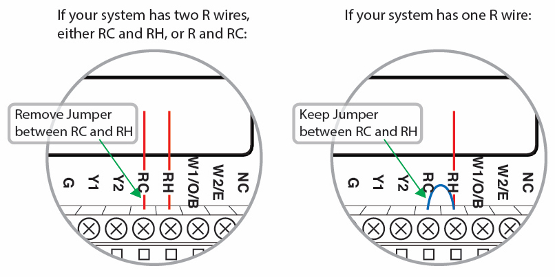
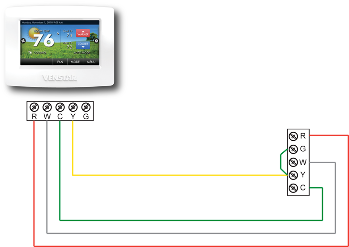
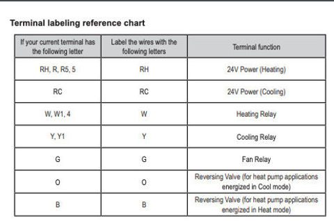
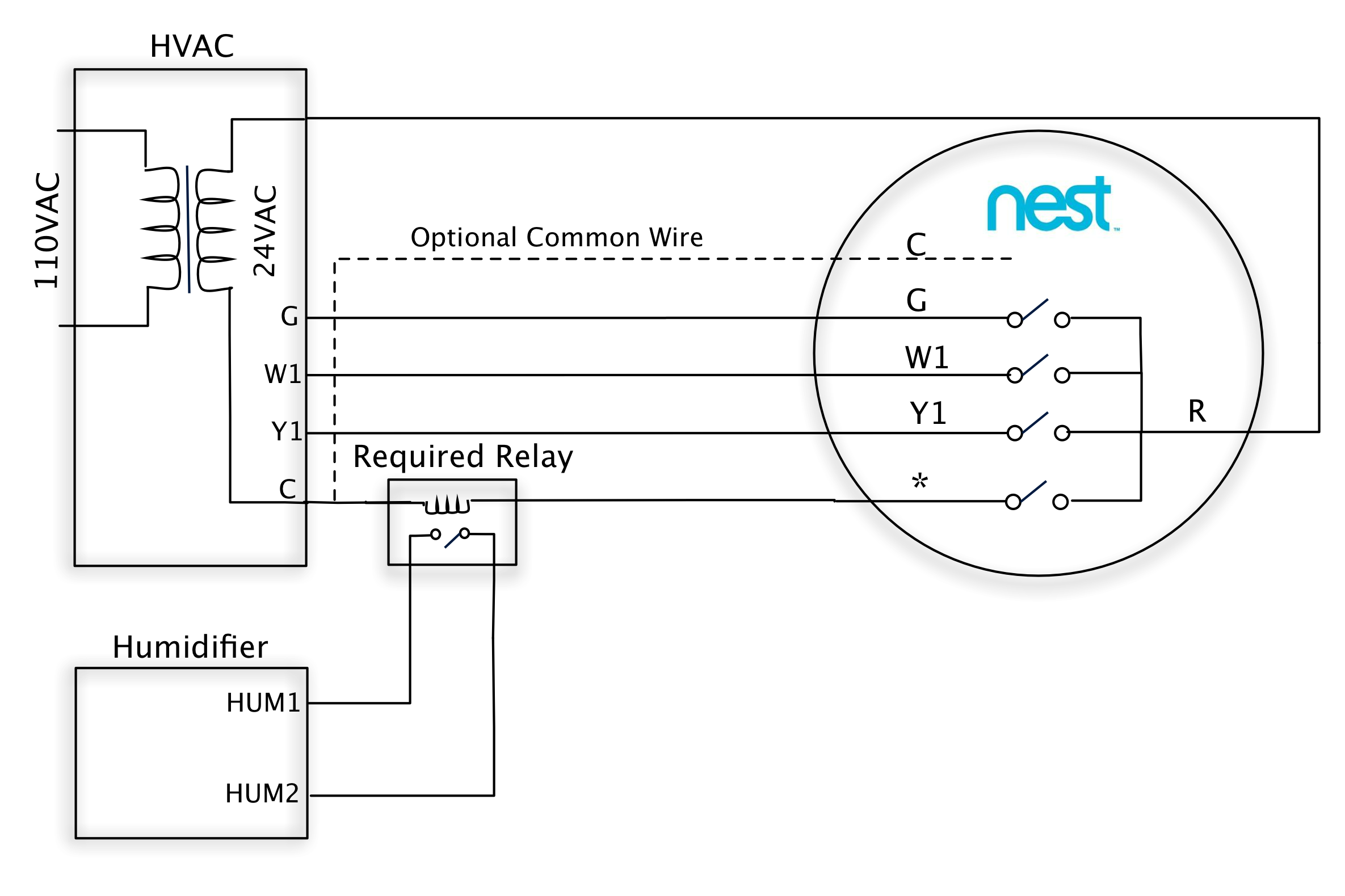
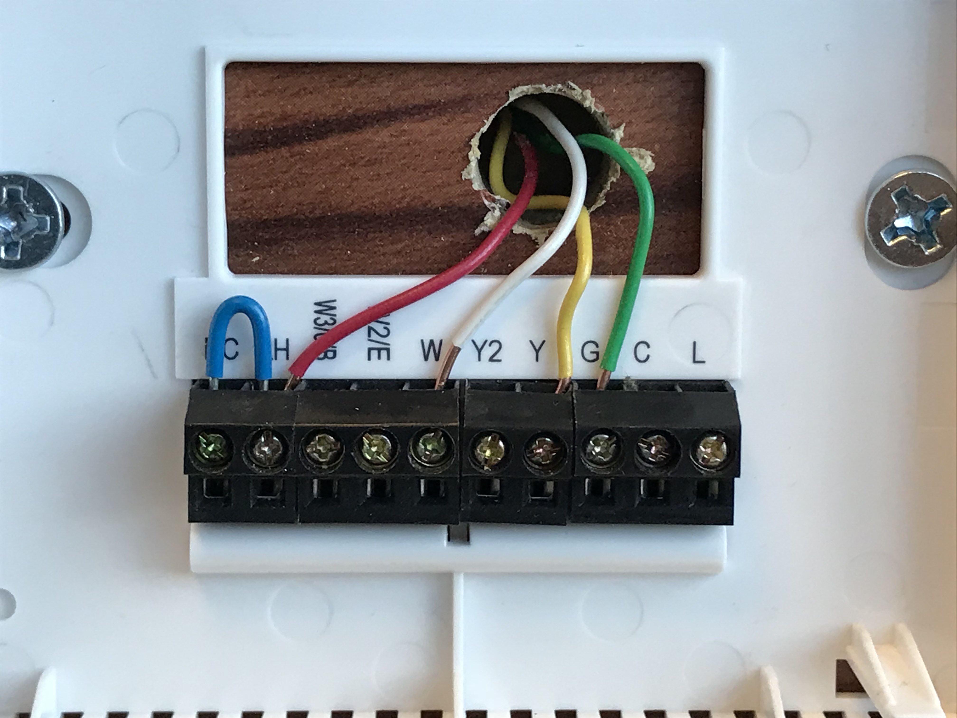
The diagram below shows how a basic 4 wire thermostat is connected as indicated by the color code chart above. The white wire connects to your heat. 4 wire or 5 wire thermostat wiring problem question. Rc red wire power 24 vac rh or 4 red wire jumpered power 24 vac. We have both a natural gas furnace and an ac unit. This wire connects to your heat pump if applicable.
4 wire thermostat wiring diagram sample. There are only four wires going into the existing thermostat red green blue white. White the white wire is what connects to the auxiliary heat on your system. But here is a list of the most common wire color mappings as seen in many four wire t stat setups. Literally a circuit is the course that enables electricity to. Here is the industry standard thermostat wire color code used for most systems.
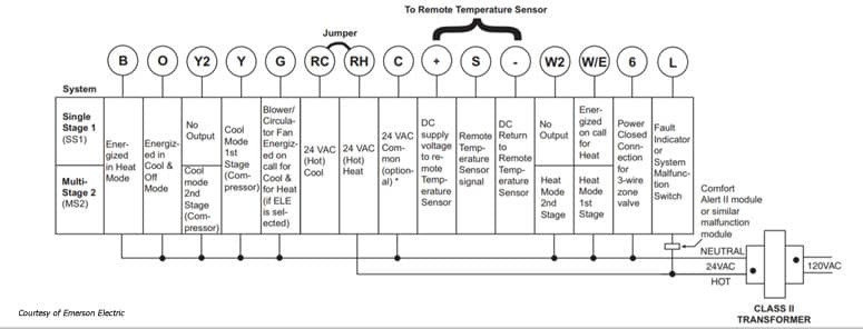
The basic heat ac system thermostat typically utilizes only 5 terminals. It reveals the parts of the circuit as streamlined shapes and the power and also signal connections in between the gadgets. Yellow the yellow wire connects to your compressor. Honeywell thermostat wiring diagram 4 wire examples the table above provides a more complete list of honeywell thermostat wiring colors and their uses. The yellow wire connects to your compressor. The green wire connects to the fan.
Gallery of Thermostat 4 Wire Wiring Diagram