After looking over the wiring diagram that came with the timing switch yes reading the instructions is a must determine what connections are required. It will typically start operating when the light is switched on but then continue to run for a pre set time after the light is turned off.
Extractor Fan Wiring Diywiki
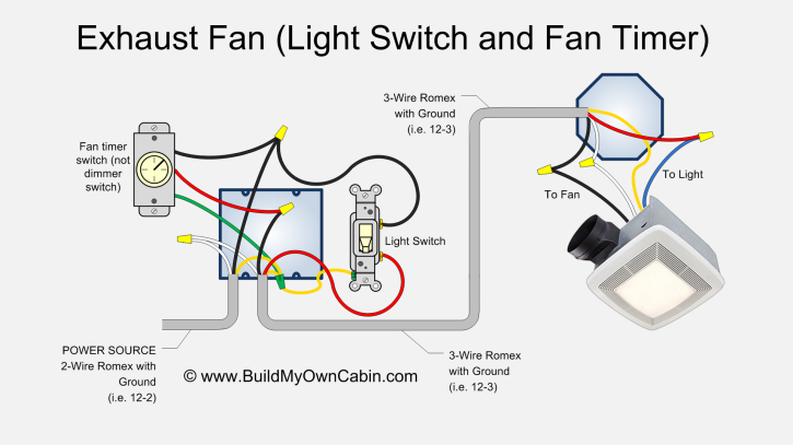
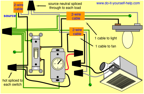
Timer fan wiring diagram. Manrose fan wiring diagram wiring diagram is a simplified adequate pictorial representation of an electrical circuitit shows the components of the circuit as simplified shapes and the gift and signal links between the devices. See page 5 for instructional drawings. From the switches 3 wire cable runs to the ceiling outlet box. It shows the elements of the circuit as simplified forms as well as the power as well as signal connections between the tools. Any help would be grateful. This type of fan is very common.
This wiring diagram illustrates the connections for a ceiling fan and light with two switches a speed controller for the fan and a dimmer for the lights. A wiring diagram usually gives suggestion just about the relative approach and promise of devices and terminals upon the devices to incite in building or servicing. Page 4 of 8 mechanical installation to install the module in an icon fan follow the instructions below. This wiring diagram shows an easy to follow configuration for a bathroom extractor fan fitted with a timer thats not going to be turned on by the existing light switch. This fan requires a neutral switch live and permanent live supply. Hi please can some explain how to wire in an xpelair 100ts extractor fan with timer.
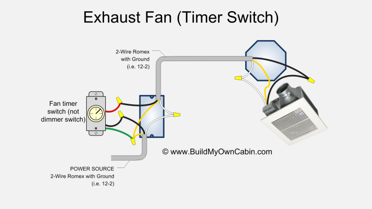
This is an excellent way to make sure the fan automatically kicks off after 20 or 30 minutes or whatever time you set. A wiring diagram is a simplified traditional photographic representation of an electric circuit. Instead we are going to install a new switch that will turn teh fan on and off. Bathroom fan wiring fan timer switch this exhaust fan or bathroom fan wiring configuration uses a fan timer switch. Fans with a timer. Collection of bathroom fan with timer wiring diagram.
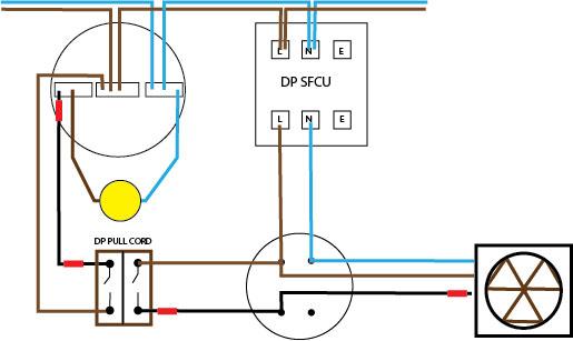
In the outlet box we will need to gain access to one of the ground screws in the back of the box to connect the timers ground wire to it. The fan can either be operated from a separate pullcord switch fitted to the ceiling of the room. Thus clearing the air in the room. Diagram a module wiring with no external switching module functionality pull cord activation only. I have 4 core cable and a isolator switch but not to sure how to wire in from the light pull cord switch. The source is at the switches and the input of each is spliced to the black source wire with a wire nut.
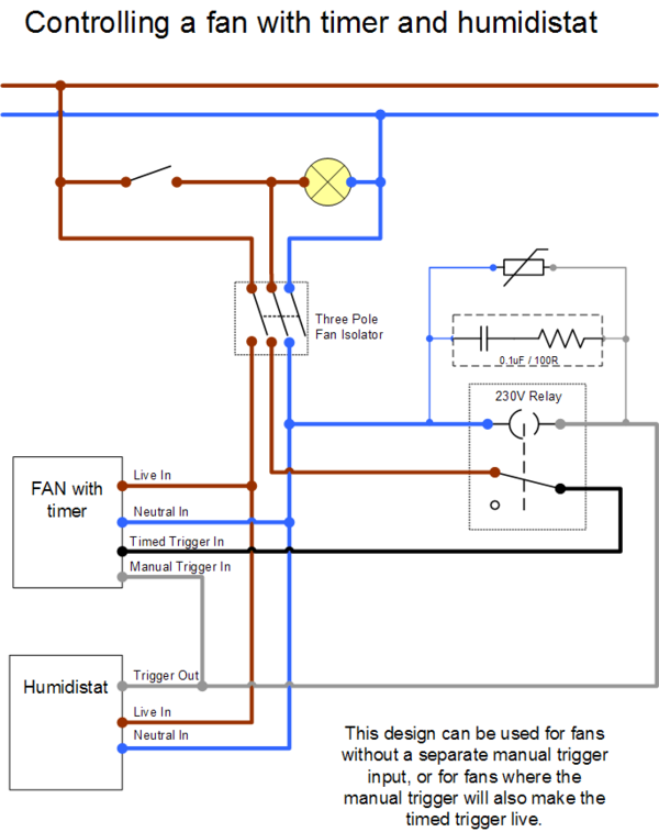
Diagram b module wiring with external switching live trigger connection used. Refer to internal wiring label and diagram 2 of this instruction for correct connection. Wiring of timer model.
Gallery of Timer Fan Wiring Diagram