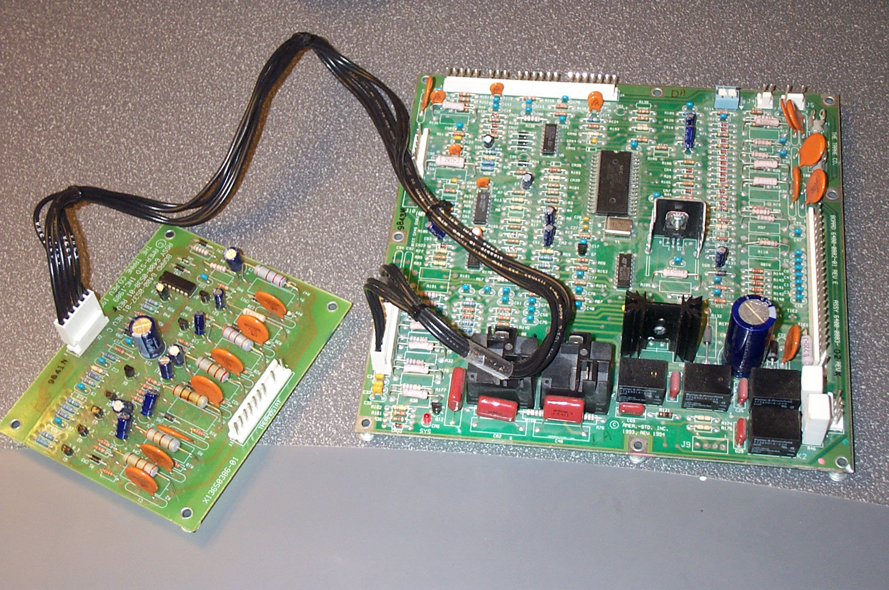
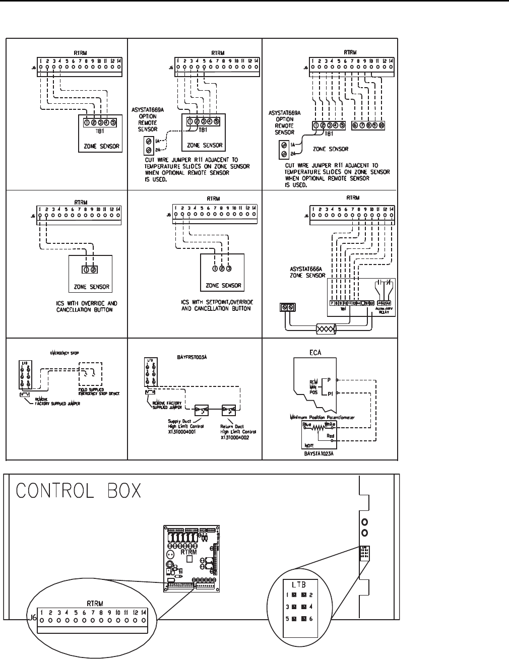
Trane voyager wiring diagram aka cti board for thermostat. Refer to wiring table 1.

Trane Interface Board
Trane cti board wiring diagram. Ignition board replacement on a trane voyager roof top unit. Onpar fait 665 views. A wiring diagram is a simplified conventional photographic depiction of an electric circuit. Cti installation for trane package unit 2000 model duration. It reveals the parts of the circuit as streamlined shapes and also the power as well as signal connections in between the devices. Does the unit have a conventional thermostat interface cti board installed.
Hvac fan motor testcontrol board replacement duration. Trane voyager wiring diagram aka cti board for thermostat. Remove unit control box. Part 1 trane circuit board replace. If no then continue on to step 3. Conventional thermostat interface connected to unitary control processor ucp 2.
If yes continue to the next step. Yes you can wire a 24vac thermostat to the unit. 1 cti board 4 screws 1 connector cable 1 wiring diagram label installation 1. Shut off all power to unit. Variety of trane ac wiring diagram. Open and lock the units power disconnect switch to prevent injury of death from electrocution or from contact with moving parts before attempting any installation or maintenance.
Refer to image 1. Trane voyager wiring diagram aka cti board for thermostat.
Gallery of Trane Cti Board Wiring Diagram