With tipper bed lifted and rested on body prob oil level must be between min and max. Back to top hydraulic oil sprays from the reservoir when the tipper is lowered.

Hydraulic Tipping Systems Dumper Truck Tipper Truck
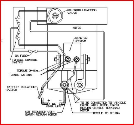
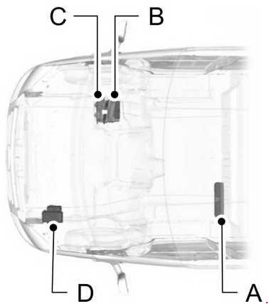
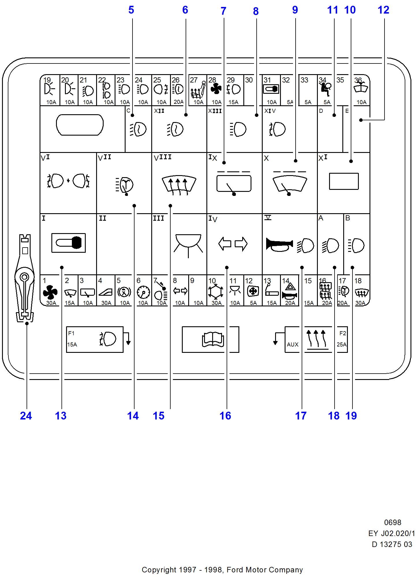
Transit tipper pump wiring diagram. Body type if in doubt please contact us. How to wire dc hydraulic power pack unit. Ford transit fuse box diagram location right hand drive a pre fuse box b standard relay box c passenger compartment junction box d engine compartment junction box. A reservoir over filled. Tipping alarm assembly box rear chassis vfs part number. Here are some details of hydraulic pump electric diagram12vdc hydraulic power unit and 24vdc hydraulic power pack hydraulic circuit diagram and electrical diagram.
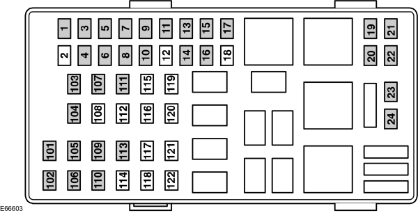
Fuel pump with fuel fired heater 25. Here is the 6 quick steps you have to make in order to. Connect the thick cable to the positive terminal of the battery. And more a wireless remote connect wire drawing also show below for single acting hydraulic power packthis wireless remote can be with a quick connector can be changed with our standard. Vfs01 14 080a to find the body type click here. 2006 2013 2000 2006 1995 2000 1992 1995 1986 1992 engine compartment fuse.
Connect the red thin wire to the universal pole of the tipper switch. Fuel pump without fuel fired heater 24. 2006 2013 2000 2006 1995 2000 1992 1995 1986 1992 left hand. On this video i will show you guys how to install a 12v double acting hydraulic pump to a dumptiltroll off trailer. Ford transit the ford transit is a range of light commercial vehicles produced by ford motor company since 1965. Back to top tipper chassis mounted buzzer fails to operate.
Sold primarily as a cargo van the transit is also built as a passenger van marketed as the tourneo since 1995 minibus cutaway van chassis and as a pickup truck. Fuse box diagram location and assignment of electrical fuses and relays for ford transit tourneo 2015 2016 2017 2018 2019. Connect the thin green wire to the down button pole of the switch and the black to the up button pole of the switch. Replace the drive motorpump unit.
Gallery of Transit Tipper Pump Wiring Diagram