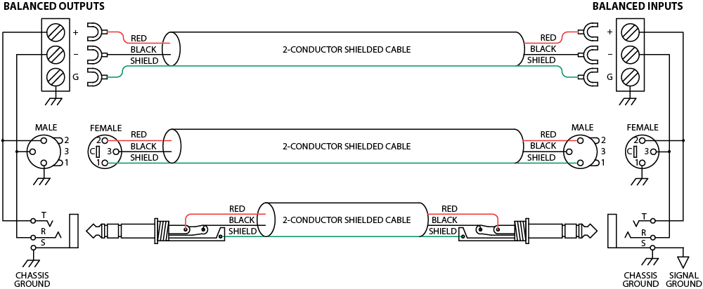
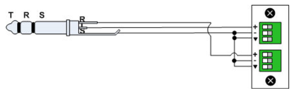
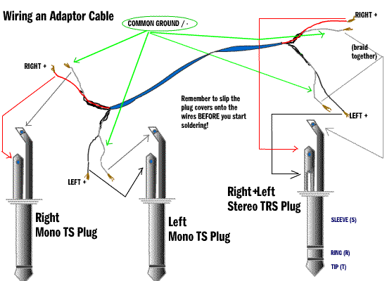
We have seven wires coming from the trs. Xlr to 14 trs connector wired for balanced mono the usual way to connect a 3 pin xlr to a 14 trs aka stereo jack plug is to use the following pin allocation.
3 5mm Audio Jack Ts Trs Trrs Type Audio Jack Wiring
Trs cable wiring diagram. Lets sort them out. Trs jack wiring diagram data wiring diagram today trs wiring diagram. Find your trs connector electrical wiring here for trs connector electrical wiring and you can print out. Xlr pin 3 to 14 plug ring. As you might imagine plugging a trs plug into a trrs socket or vice versa will result in an electrical short between one channel and ground. Nov 10 trs jack wiring audio making a 4 pole trrs to 3 5mm stereo mic rhjebbushco.
Wiring diagram also provides helpful suggestions for tasks that may need some extra equipment. So using this you can only listen music but cant talk on calls. This wiring configuration gives you a balanced mono audio cable. These types of audio jacks supports stereo sound and but doesnt supports microphone. Xlr pin 2 to 14 plug tip. Search for trs connector electrical wiring here and subscribe to this site trs connector electrical wiring read more.
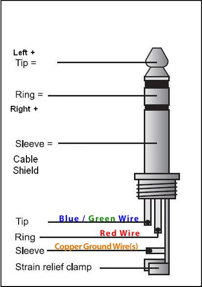
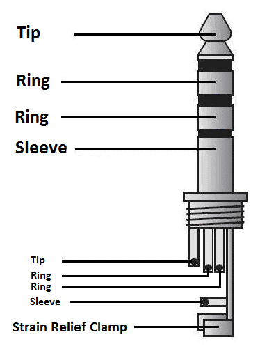
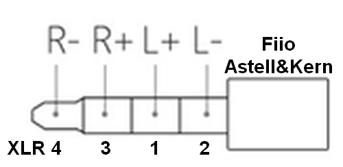
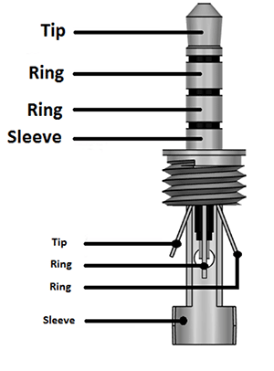
Below is the pinout of trs type male audio jack. The diagram above shows a regular pair of earbuds plugged into an iphone trrs socket. Trs type male audio jack. The tip is the end of the plug the ring is the small middle section located between the two plastic dividers and the sleeve is the rest of the metal part of the plug. Wiring diagrams trs gray 8 way plug. A trs connector tip ring sleeve also called an audio jack phone jack phone plug jack plug stereo plug mini jack mini stereo or headphone jack is a common analog audio connectorit is cylindrical in shape typically with three contacts although sometimes with two a ts connector or four a trrs connector.
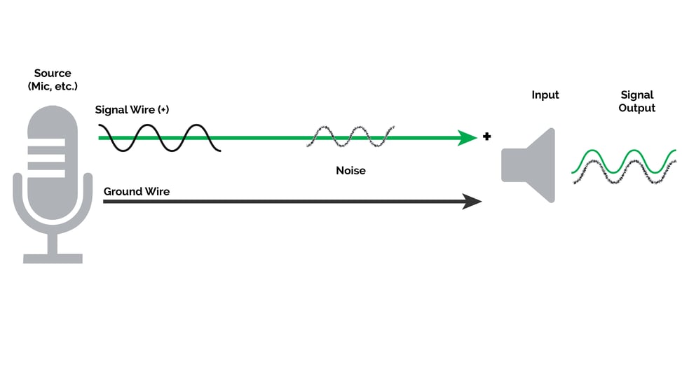
For the most part a short like this isnt a great concern. Xlr pin 1 to 14 plug sleeve. 3 5mm trrs jack wiring diagram a pcb layout is the resulting design from taking a schematic with specific components and determining how they will physically be laid out on a printed circuit board. Here in the name of trs t stands for tip r stands for ring and s stands for sleeve. It was invented for use in telephone switchboards in the 20th century and. A trs plug can be used for.
A stereotrs short for tipringsleeve 14 inch plug looks like an analog stereo headphone plug. This e book even includes recommendations for extra provides that you might need as a way to end your tasks. First lets look at the pin diagram of the gray 8 way connector coming from the transmission range sensor. The wires coming out of the trs are different colors than those on the harness side.
Gallery of Trs Cable Wiring Diagram