Each wire set contains two insulated and one bare wire. As described the wiring will require four wires for the connections to the time switch.

User S Manual Version 5 0 Manualzz
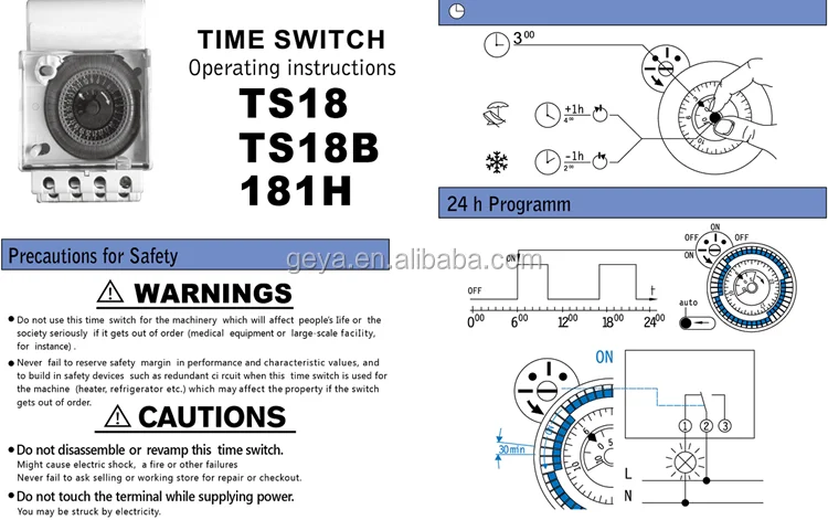
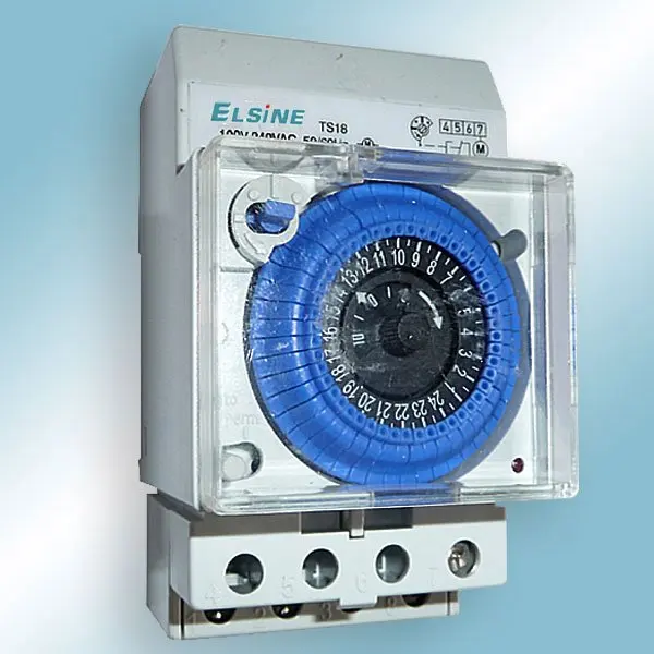
Ts18 timer wiring diagram. Subsequent depression will re start the timer. How do i wire a timer switch for lighting. Ron in oregon asks. Step 5 identify each wire terminal using the numbered labels 1 through 4 for line and load terminal identification. Requirements for most digital timer switches electrical question. 100 240vac 5060hz ts18 time switchts18 ts18b 181h with manual control onoff override control and permanent on.
24 hour timer 12 volt 24 hour timer wiring diagram 24 hour timer wall switch 24 hour timer with dry contacts. The timer uses a gr label to identify its green colored ground screw. Timer activates when button is depressed. Mce electric the leading electrical products distributor in south africa. Identify and locate the pool pump timers wire terminals using the timers schematic as a guide. When wiring a mechanical time switch begin by connecting the ground wires.
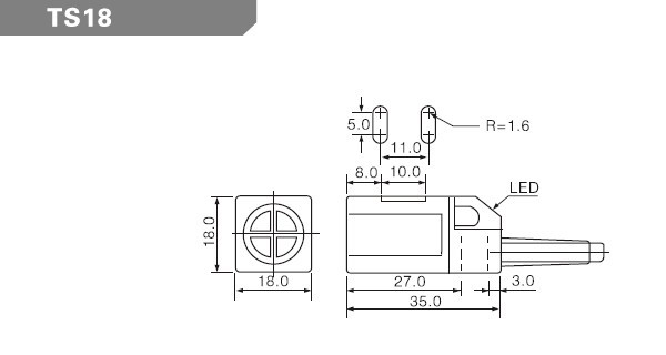
Two wire sets enter the timer. A ts 3t ts 5t plate led wiring colored lead designation notes. I bought a quality sul 181h pool timer switch and im trying to connect it. I just bought a pass seymour rt1w digital timer switch to replace my simple single pole switch. Ts18 time switch a. 24 hour timer diagram 24 hour timer download 24 hour digital timer switch.
I saw advise on another thread that was posted earlier this year that i should connect the live wire from the mains. Analogue power reserve b. 24hrs timer switch in explaining in tamil and circuit diagram also very simple method how to website category mechanical timers how to setup a timer instructional videos timer energy. The schematic located on the inside of the pool timers lid shows the wire terminals positions their functions and labels them. The wire terminals with the line designation connect to the wires coming from the circuit breaker and the wire. Intermatic prints the labels above each terminal.
This is done by attaching one end of grounding pigtail wire to the green ground screw on the time switch then joining the other end of the pigtail to the incoming and outgoing circuit ground wires using a wire connector wire nut.
Gallery of Ts18 Timer Wiring Diagram