Some appliances will only have two wires live neutral. Unscrew one screw from the main cable holder and remove the screw completely.
Iso 7638 Lead
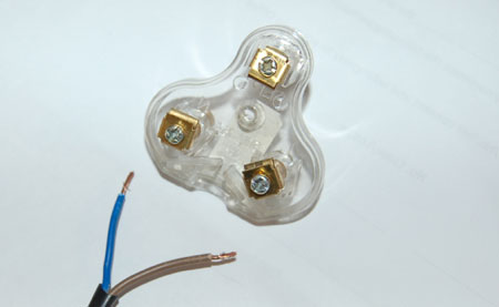
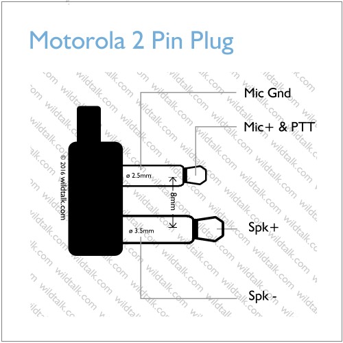
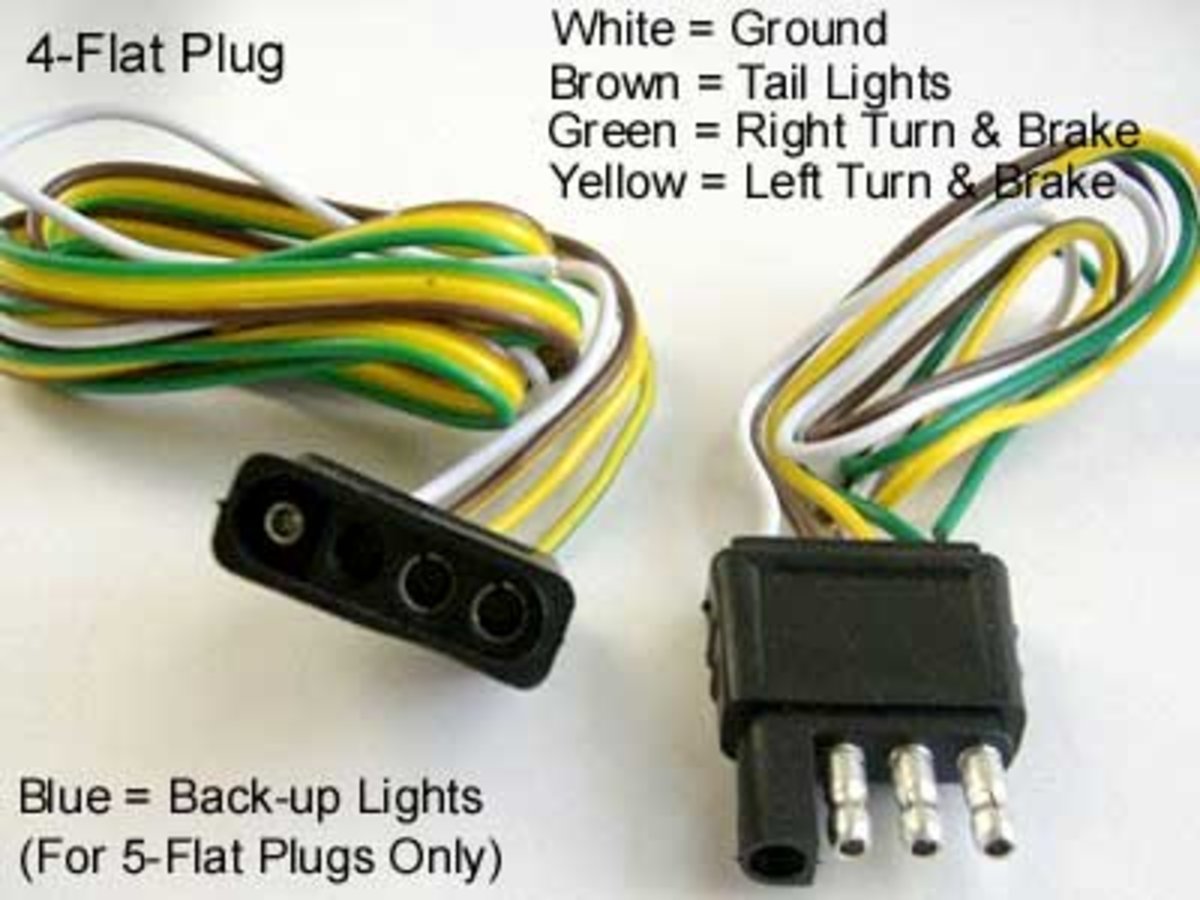
Two pin plug wiring diagram. Below is the generic schematic of how the wiring goes. The plugs have three round pins arranged in a triangle with the larger top pin being the earthing pin. One prong connects to the hot wire which is the live circuit wire and one connects to the neutral wire which is the one that completes the electrical circuit. Use this 4 pin trailer wiring diagram to properly wire your 4 wire trailer plug. If the plug has a cardboard wiring diagram over the pins make sure this is removed before using the appliance. The plugs are polarised and unfused.
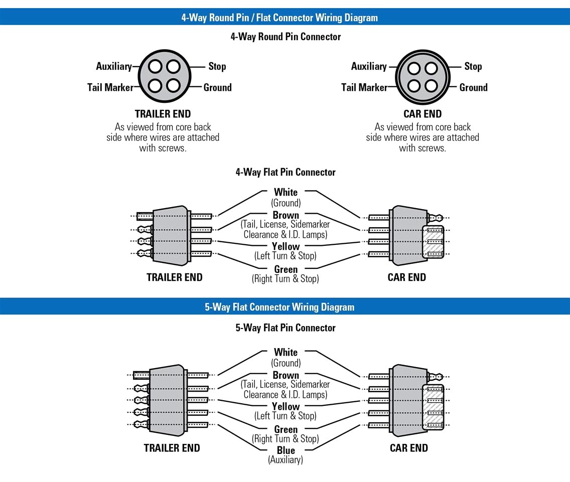
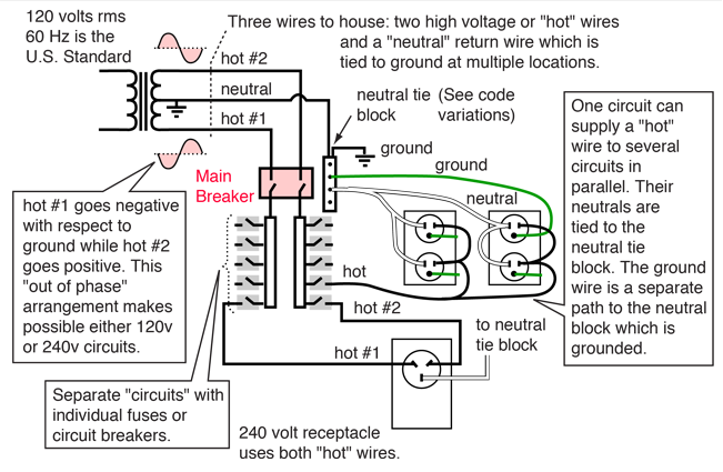
Following the standard method for wiring a trailer connector is vital to the safety of your vehicle while towing. Alternating current switches directions 60 times a second so you can treat the two wires as identical. Note that this type of 4 pin connector is less common that 4 pin flat connector. Some 120 volt plugs have a third prong for grounding the appliances they serve and plugs for 240 volt appliances which require two hot wires have four prongs. The longer third plug rotated 90 degrees from the other two is for ground. Connecting the wrong color wires will result in mismatched taillight functions and confusion on the road.
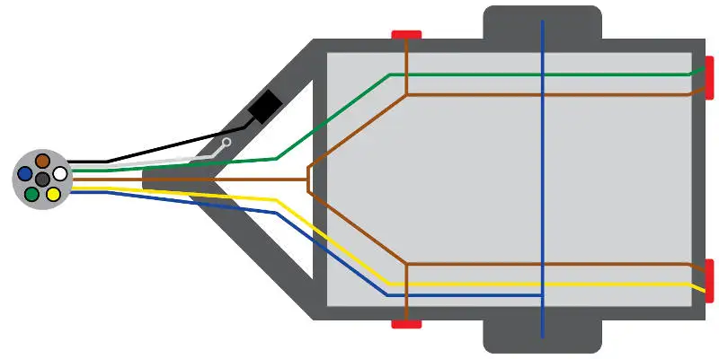
How to fix or replace broken electrical plug and wire step by step process explained tutorial duration. Most plugs use a small plastic gate secured by screws to hold the cable in place. Wire them to the left and right plugs. Bs 546 two pole and earthing pin plugs socket outlets and socket outlet adaptors for ac 50 60 hz circuits up to 250v describes four sizes of plug rated at 2 a 5 a type d 15 a type m and 30 a. Four pin trailer wiring install wiring diagram info in electric by magnus sellén 9 august 2019 leave a comment many people often have difficulties with the wiring of their trailer and even after several attempts they still dont seem to get it right. These are double insulated and do not rely upon the earth wire for protection.
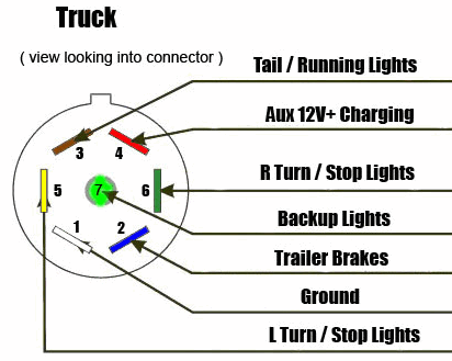
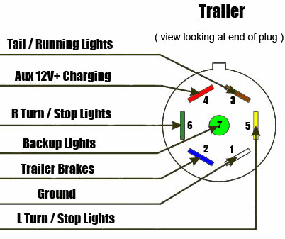
In the trailer wiring diagram and connector application chart below use the first 5 pins and ignore the rest. Make sure the wire is held in place around the outer sheath. You can leave it disconnected for a lamp. 4 pin trailer wiring diagram. Close the gate again and secure the screw back into place. Swing the gate open and place the wire in the holder.
This type of connector is normally found on utvs atvs and trailers that do not have their own braking system. Above we have describes the main types of trailer wiring diagrams. If your truck has a built in 7 pin socket but you only need 5 of the pins. Use the 7 pin connector anyway see below and just leave out the last 2 wires. Knowledge 360 19798 views.
Gallery of Two Pin Plug Wiring Diagram