Various connectors are available from four to seven pins that allow for the transfer of power for the lighting as well as auxiliary functions such as an electric trailer brake controller backup lights or a 12v power supply for a winch or interior trailer lights. The image above shows a single axle trailer and the next image shows wiring for tandem axles.

Trailer Wiring Diagram On Chevy Pickup Gm 7 Pin Trailer Plug
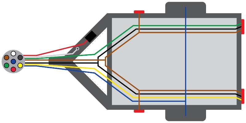
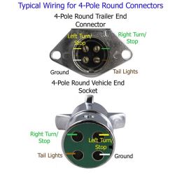
Typical trailer wiring diagram. Right turn signal stop light green left turn signal stop light yellow taillight license side marker brown and a ground white. Above we have describes the main types of trailer wiring diagrams. As the name implies they use four wires to carry out the vital lighting functions. Only the blue brake and white ground wires are different. They also provide a wire for a ground connection. 4 way trailer connectors are.
The diagrams below show the typical trailer wiring for 4 pin flat connectors all the way to 7 pin round connectors. Trailer wiring diagrams 4 way systems 4 way flat molded connectors allow basic hookup for three lighting functions. Trailer wiring diagrams trailer wiring connectors. 4 way trailer connectors are typically used on small trailers such as boat snowmobile utility and other trailers that that do not use brakes. To connect the electric system of your trailer to the vehicle you will be using special connector. Complete with a color coded trailer wiring diagram for each plug type this guide walks through various trailer wiring installation solution including custom wiring splice in wiring and replacement wiring.
It reveals the parts of the circuit as streamlined shapes as well as the power and also signal links in between the gadgets. This chart is a typical guide wire colors may vary based on manufacturers. The four wires control the turn signals brake lights and taillights or running lights. 4 way tow vehicle side. It is important to note that the white wire is the ground wire you will notice this even when you buy lights. Collection of travel trailer wiring schematic.
Extrapolate the same expansion for additional axles. If your vehicle is not equipped with a working trailer wiring harness there are a number of different solutions to provide the perfect fit for your specific vehicle. These 2 wire diagrams fit the needs for most trailers. A faulty and unsecured ground wire is often the. Trailer wiring diagrams trailer wiring connectors various connectors are available from four to seven pins that allow for the transfer of power for the lighting as well as. A lot of led lights come with black and white wires and people can easily confuse the black wire for the ground.
Four pin trailer wiring install wiring diagram info in electric by magnus sellén 9 august 2019 leave a comment many people often have difficulties with the wiring of their trailer and even after several attempts they still dont seem to get it right. Typical trailer wiring diagram and schematic. Use a circuit tester to verify connections. 4 pin trailer wiring diagram. A wiring diagram is a streamlined traditional photographic depiction of an electric circuit. Below is the generic schematic of how the wiring goes.
Gallery of Typical Trailer Wiring Diagram