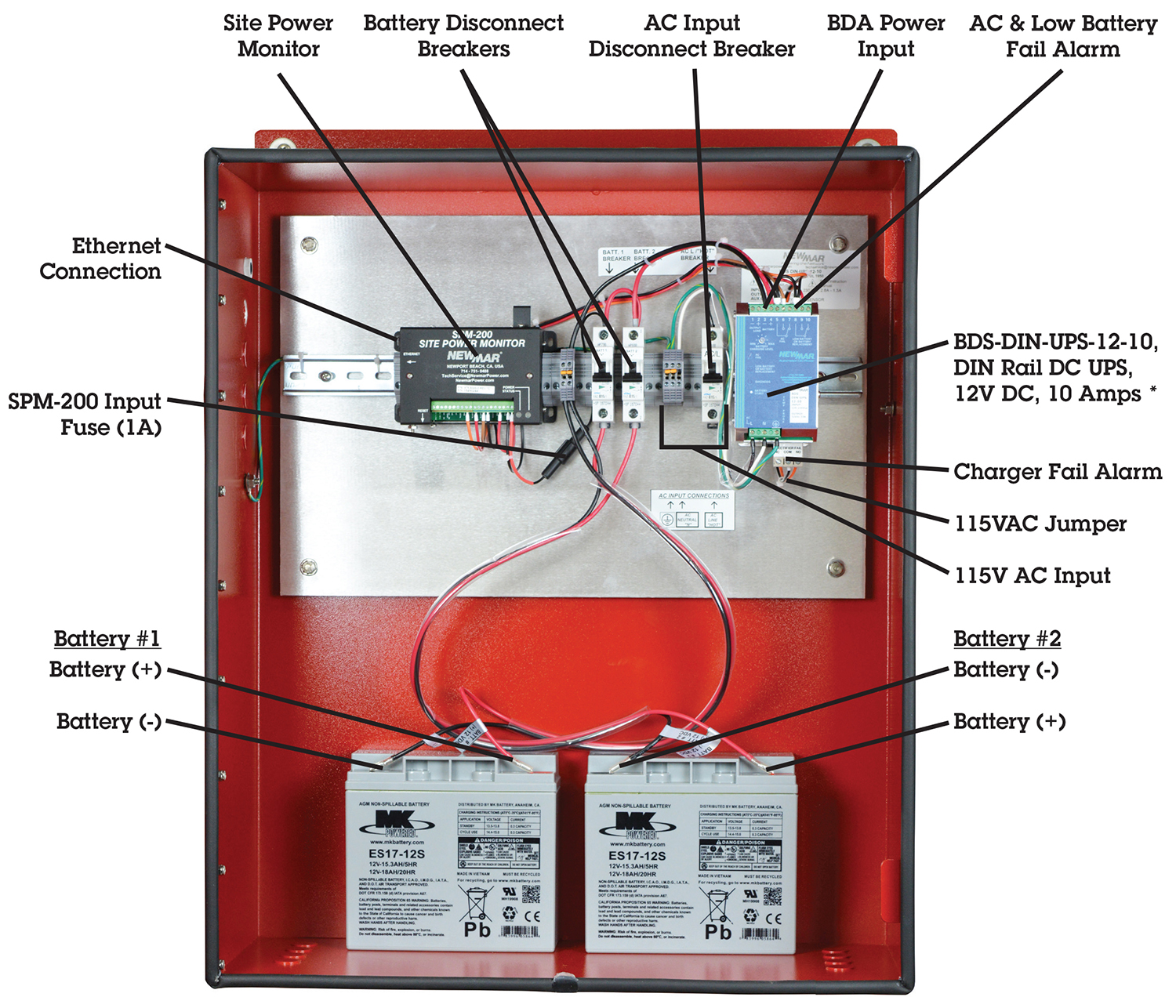
Wiring diagrams for hardwire ups battery backup ups uninterruptible power supply systems in the following table can be directly wired to either a 120240 split phase panel 6k 10k single phase models or a 120208y 3 phase panel 10k 15k 20k 30k 40k 3 phase models. Collection of ups maintenance bypass switch wiring diagram.
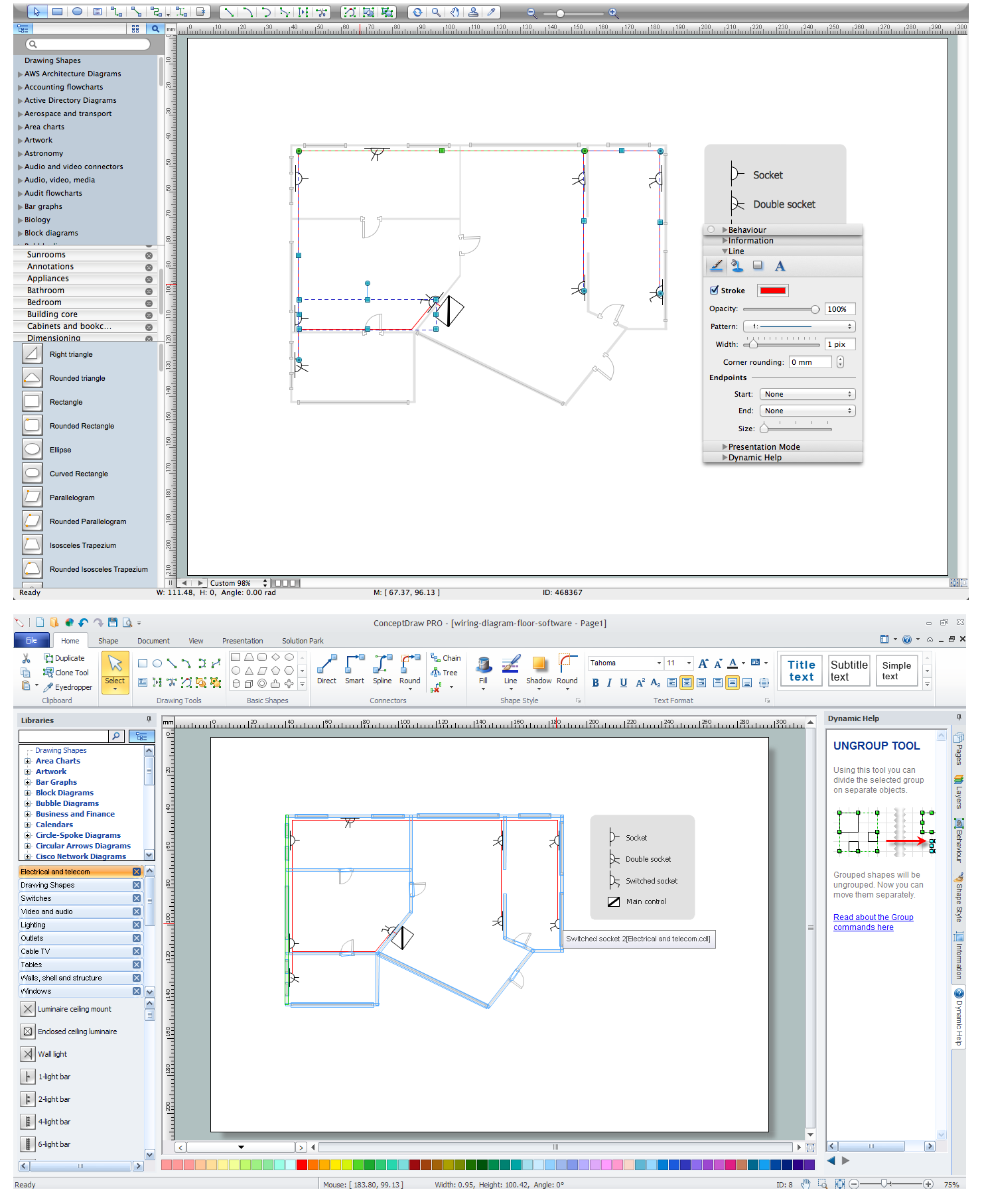
Lighting Circuits Connections For Interior Electrical
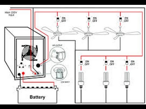
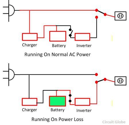
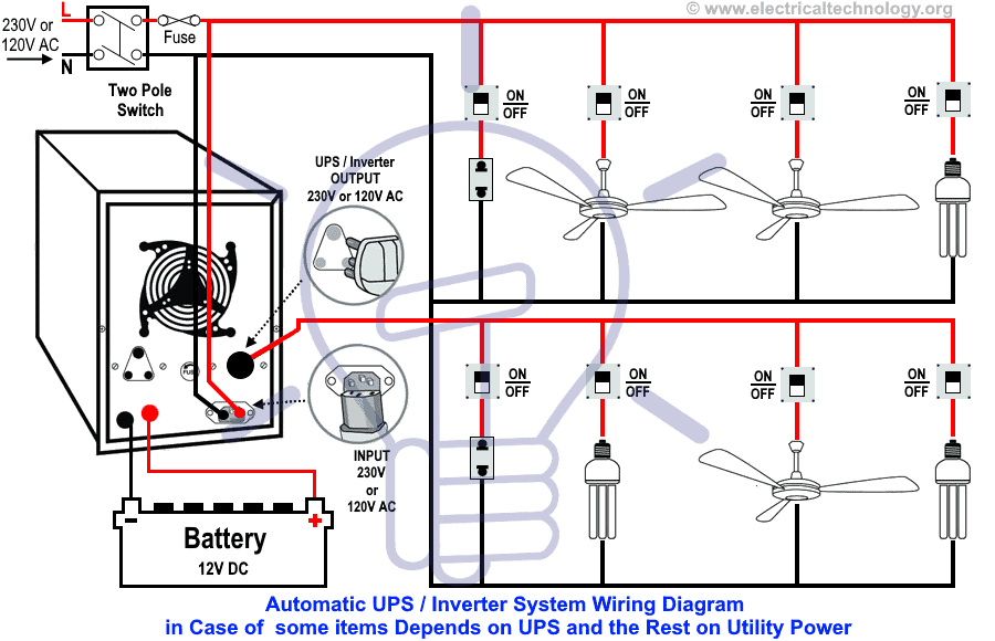
Ups system wiring diagram. In this wiring system the main power is connected to the double pole dp mcb. The ac power 220v is entered to through input of transformer t1 to reduce voltage as 9vac then wire connected to four diode d1 d4 as bridge rectifier became to 11vdc. In the following ups inverter wiring diagram it clearly shows that when the utility power is not available the connected ceiling fan two light bulbs and a 2 pin socket will be operated through batteries and ups as the output live phase wire of the ups inverter is only connected to them and the rest will be off due to the absence of main power. Ups inverter wiring diagram with auto manual changeover switch system. A wiring diagram is a simplified standard pictorial depiction of an electrical circuit. It shows the elements of the circuit as simplified forms and the power as well as signal connections in between the gadgets.
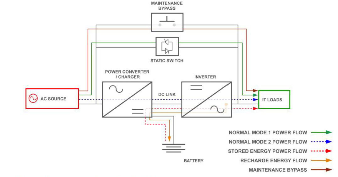
Ups uninterruptible power supply is a device used for protection against over voltage under voltage. Automatic ups system wiring diagram in case of some items depends on ups and rest depends on main power at office or home. Related electrical wiring tutorial. This simple and cheap 6 volt power supply circuits with a 6v backup battery system or 6v ups circuit diagram. Provide continuous supply in case of supply outage protection against voltage spikes frequency fluctuation and against distortion in voltage wave form. A wiring diagram typically provides information regarding the relative position and also plan of tools and also terminals on the tools in order to help in building or servicing the tool.
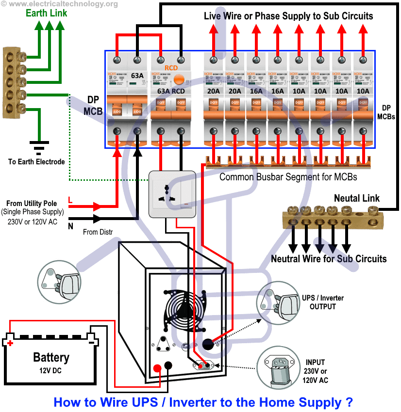
Manual ups wiring diagram with change over switch system. Automatic ups system wiring circuit diagram for home or office new design with one live wire also read. Two wires as phase and neutral from the dp main switch is directly connected to the ups as input while the output of the ups has been connected to the rcd residual current device and other related single pole circuit breakers then. Now according to the below ups connection diagram connect an extra wire phase to those appliances where we have already connected phase and neutral wires from power house db ie two wire as phase live as shown in the below fig.
Gallery of Ups System Wiring Diagram