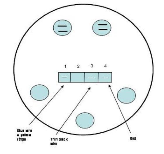
Part numbers forhe t vdo generator sensor is part 340 001vdos inductive sensor is part 340 020 1. Al or the spot where the negative battery fuse box.
41b29 Vdo Tachometer Wiring Diagram Diesel Epanel Digital Books
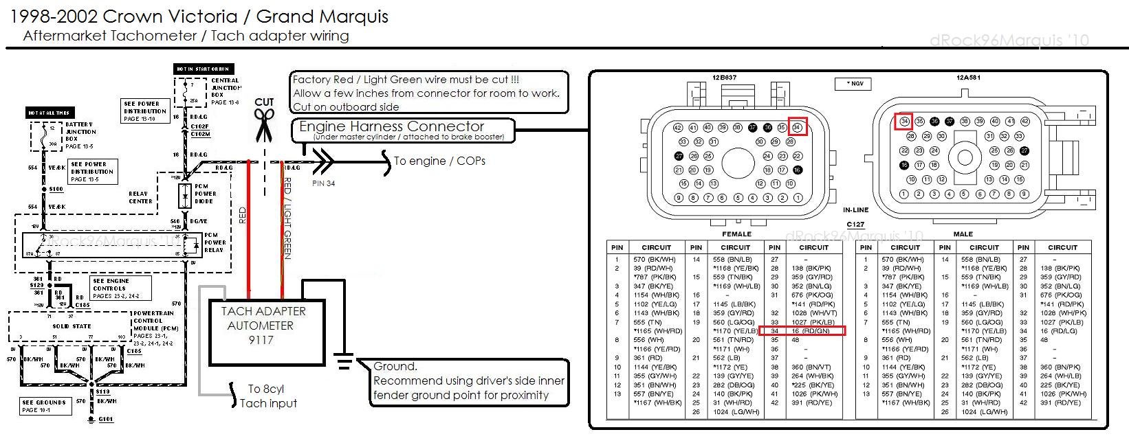
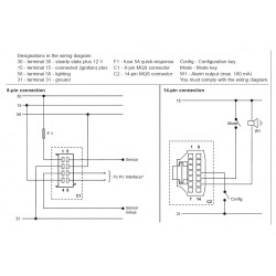
Vdo tachometer wiring diagram. 8 pin connection f1 fuse 5a quick response c1 8 pin mqs connector you must comply with the wiring diagram. This sensor is avail able from your auto parts dealer. The 3¹₈ 80 mm tachometer requires a hole diameter of 3¹₈. And eter either the ac tap on the alternator or the terminal 1 of f the tachometer marked and itched 12 volt source to the terminal on the back of the gauge marked. Diagram f fine adjustment of the vdo tachometer when used with an alternator compare the vdo tachometer reading with that of a reference tachometer. When the vdo tachometer reading.
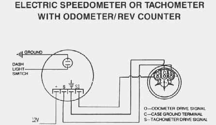
The ground œ wire is also run in series including the light socket ground. Refer to the wiring diagram diagram g. Vdo tachometer is not included. Measuring instruments vdo tachometer with counter installation instructions manual 11 pages measuring instruments vdo cancockpit series product manual. Iring your new vdo tachometer is a simple and straightforward procedure as shown in diagram d. Diagram c proper mounting of the eliminator rfemf filter on the back of the tachometer tachometer installation and operation instructions addendum for comp eliminator ii tachometer siemens vdo allentown pennsylvania usa the instructions for operation and electrical wiring for this tachometer follows.
Adjust the potentiometer on the back of the tach. New generation 2009 flexible instrumentation with can bus technology 174 pages. Refer to diagram b for dimensions. Wire gauges in series from a positive accessory to a source which is not already overloaded with fans air conditioning and such. Related manuals for vdo tachometer. Diagram e proper wiring of the vdo programmable tachometer with typical ignition systems ˇˆ ˇ.
The final ground run using 14 gauge wire should be connected to a good. Tachometer without display 13 gb 14 connector set 8 pin a2c59510850 30 terminal 30 steady state plus 12 v 15 terminal 15 connected ignition plus 58 terminal 58 lighting 31 terminal 31 ground designations in the wiring diagram.
Gallery of Vdo Tachometer Wiring Diagram