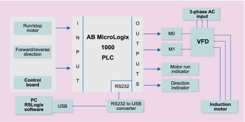
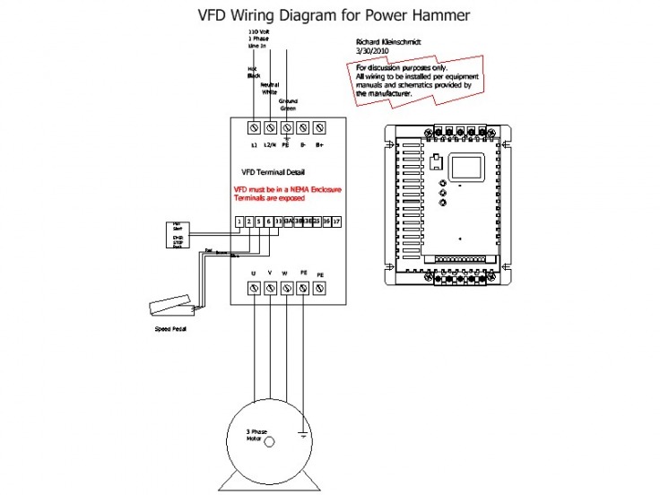
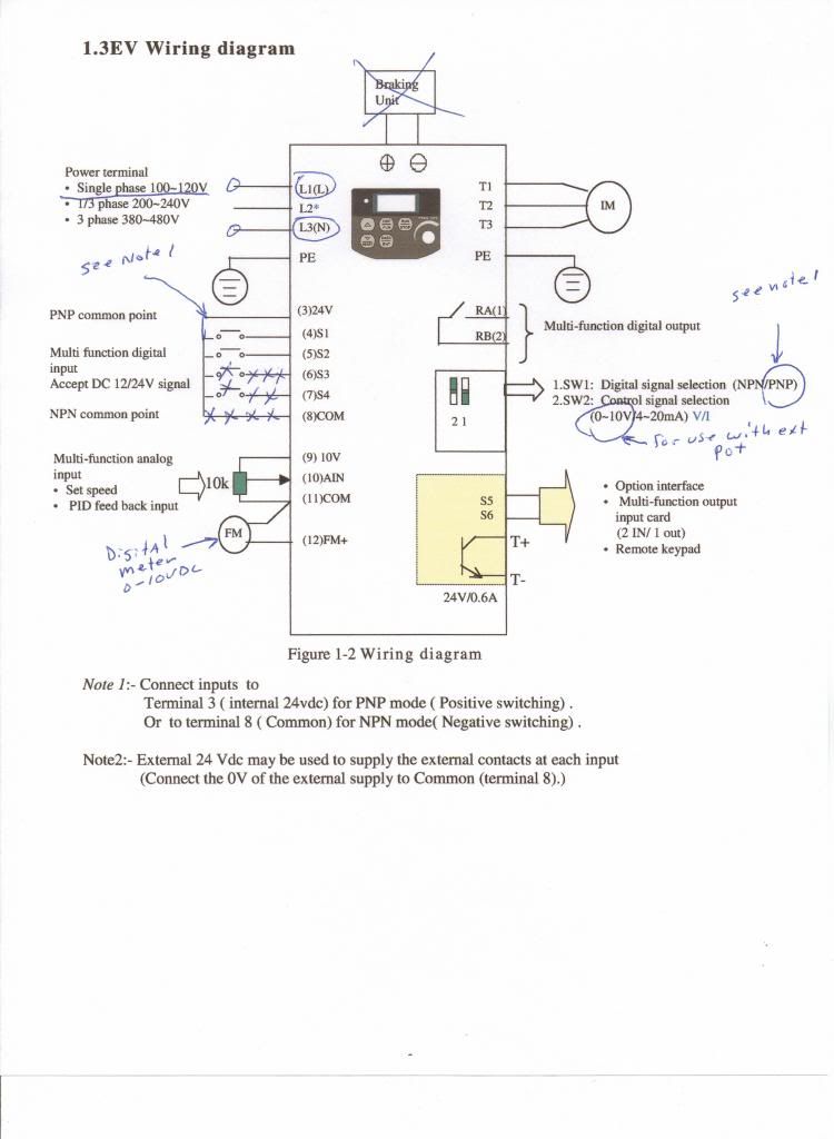
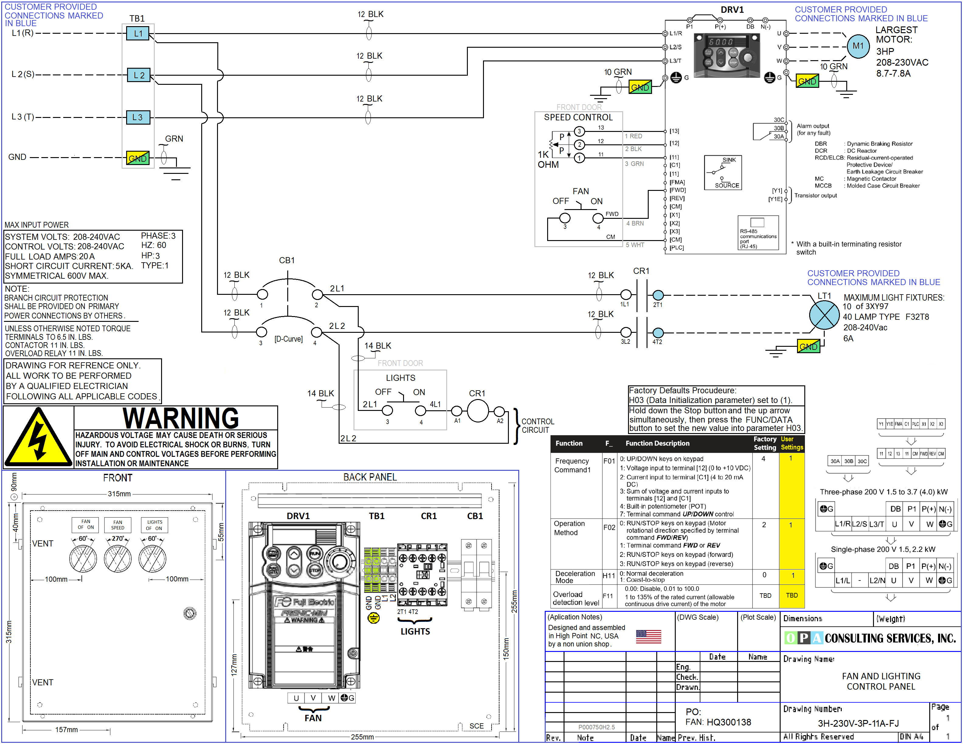
T1 t2 t3 used for giving 3 phase input to vfd and connecting motor to it and wires coming out of m0 m1 and gnd. The vfds showed in the video are the d720s 230v single phase and the d720 230v three phase.
Variable Frequency Drive In Pulp Amp Paper Machines
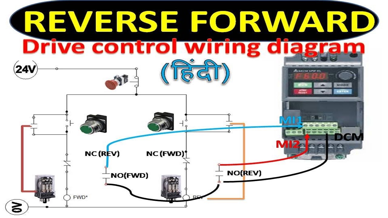
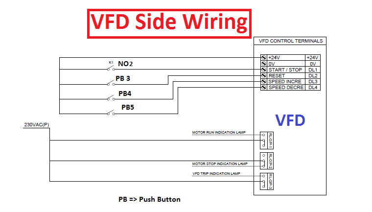
Vfd control wiring diagram. In this video we used the very popular mitsubishi d700 series vfd showing single phase and three phase wiring instructions. A wiring diagram is a streamlined traditional pictorial representation of an electrical circuit. Some vfds are having only one feedback relay that time you just use the same for trip feedback. When you press the on push k1 contactor will hold and k1 no1 become nc. The acs adjustable speed ac drive should only be installed by a power circuit terminals u1 v1 w1 and u2 v2 w2 and depending on the following diagram shows the terminal layout for frame size r3 which invfd wiring. A wiring diagram usually gives details about the loved one position and setup of gadgets and also terminals on the devices in order to help in structure or servicing the gadget.
2 the control line and the main circuit cable laying. Pin out connection diagram for vfd m fig. For programming the vfd m. Switch on the 3 phase power supply. How to control vfd with push button switch terminal controlwire control duration. Assortment of vfd wiring diagram.
Check connections of l1 l2 l3. Ato automation 31830 views. To read a wiring diagram first you must know what fundamental elements are included inside a wiring diagram and which pictorial symbols are widely used to represent them. K1 no1 pb3 pb4 pb5 should be of potential free contact. A wiring diagram is a simplified standard photographic depiction of an electric circuit. Control circuit terminals wiring 1 as the low voltage vfd over current of the control circuit cables is generally small so the size of the control cable can be standardized in order to avoid the interference caused by malfunction the control cables should be twisted shielded wires.
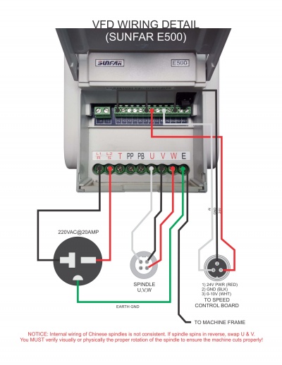
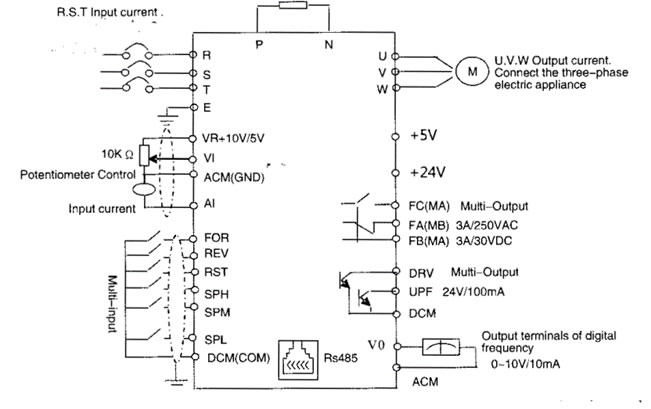
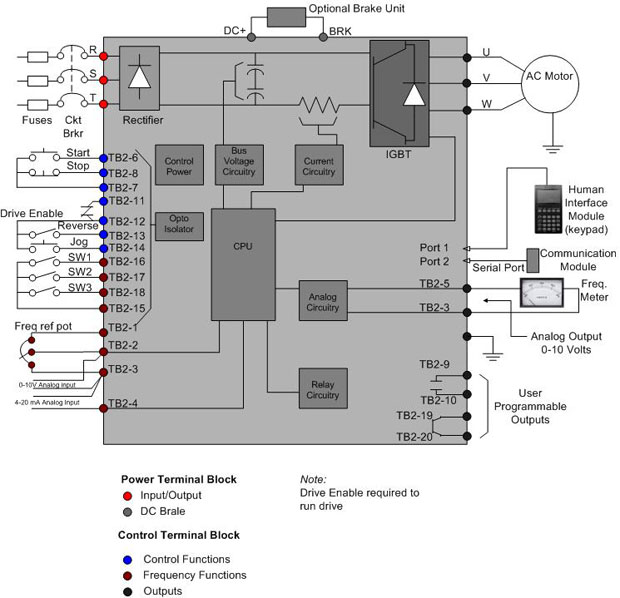
The common elements inside a wiring diagram are ground power wire and connection output devices switches resistors logic gate lights etc. Sizing the sizing of the control wire is again going to be based off the current load and voltage that will be on them but it is suggested that it is rated for 600v. Vfd start stop wiring diagram. Main circuit wiring variable frequency drive wire input to terminals l1 l2 and l3 for three phase input. Collection of abb vfd wiring diagram. Controlling a digital keypad on delta vfd m steps for complete motor control.
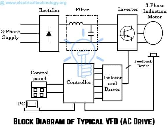
Vfd start stop wiring diagram. It shows the parts of the circuit as streamlined forms and the power and also signal links between the gadgets. It reveals the components of the circuit as simplified forms and also the power as well as signal connections in between the gadgets. Learn the basic wiring of variable frequency drives vfd with our electrician steve quist. We strongly recommend using a certified electrician to set up your vfds. Connect or do wiring as per vfd side drawing you take 24 v from the vfd pcb directly.
Gallery of Vfd Control Wiring Diagram