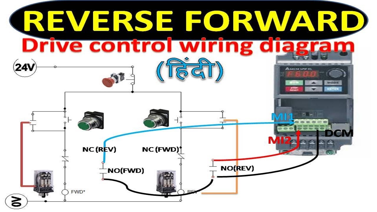
Connect or do wiring as per vfd side drawing you take 24 v from the vfd pcb directly. February 7 2019 by larry a.
Hvfdsd3c0030g100a
Vfd wiring diagram. A wiring diagram is a simplified standard photographic depiction of an electric circuit. Assortment of vfd wiring diagram. By headcontrolsystem collection of abb vfd wiring diagram. To read a wiring diagram first you must know what fundamental elements are included inside a wiring diagram and which pictorial symbols are widely used to represent them. A wiring diagram is a streamlined traditional pictorial representation of an electrical circuit. In this video we used the very popular mitsubishi d700 series vfd showing single phase and three phase wiring instructions.
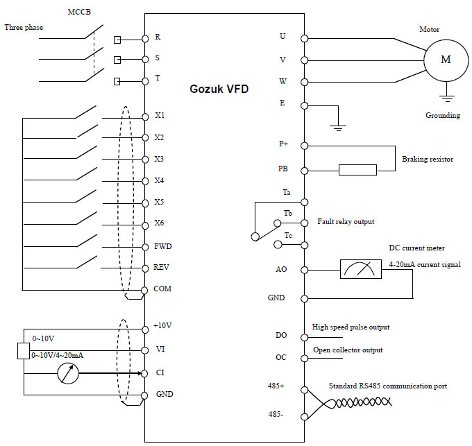
When you press the on push k1 contactor will hold and k1 no1 become nc. How to wire circuit protection breaker and fuse duration. It shows the parts of the circuit as streamlined forms and the power and also signal links between the gadgets. Learn the basic wiring of variable frequency drives vfd with our electrician steve quist. A wiring diagram is a streamlined standard photographic depiction of an electric circuit. 1 the vfds three phase ac input terminals rl1 sl2 tl3 the power lines input terminals connect to 3 phase ac power through line protection or leakage protection breaker it does not need to consider the connection of phase sequence.
Wellborn variety of vfd motor wiring diagram. It reveals the elements of the circuit as streamlined shapes and also the power and signal connections between the devices. Wiring information is located in the powerflex series ac drives installation instructions publication in disclaimer this knowledge base web site is intended to provide general technical information on a particular subject or subjects and is not an exhaustive treatment of such subjectsab on vfd wiring diagram wiring libraryrockwell automation. Vfd start stop wiring diagram. We strongly recommend using a certified electrician to set up your vfds. The vfds showed in the video are the d720s 230v single phase and the d720 230v three phase.
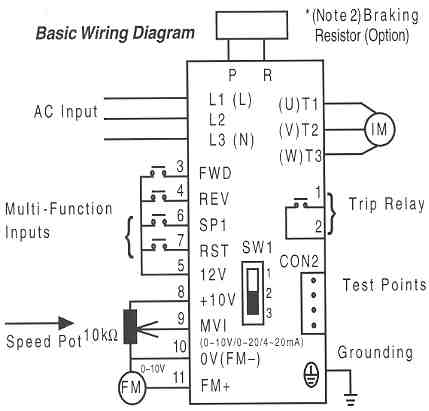
The vfd main circuit terminals shown as below figure. Sizing the sizing of the control wire is again going to be based off the current load and voltage that will be on them but it is suggested that it is rated for 600v. It reveals the components of the circuit as simplified forms and also the power as well as signal connections in between the gadgets. Starting a vfd with 2 wire start duration. K1 no1 pb3 pb4 pb5 should be of potential free contact. The common elements inside a wiring diagram are ground power wire and connection output devices switches resistors logic gate lights etc.
Gallery of Vfd Wiring Diagram


.png)