A wiring diagram is a streamlined traditional photographic representation of an electrical circuit. February 11 2019 by larry a.

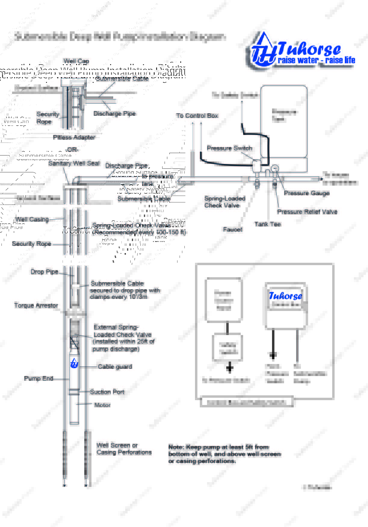
Green Road Farm Submersible Well Pump Installation
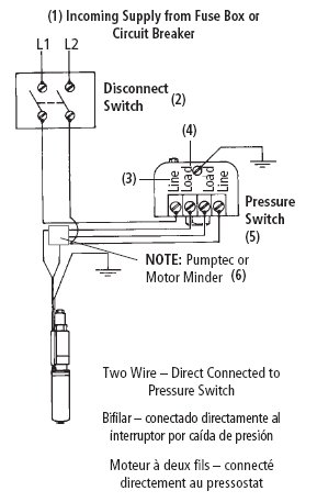
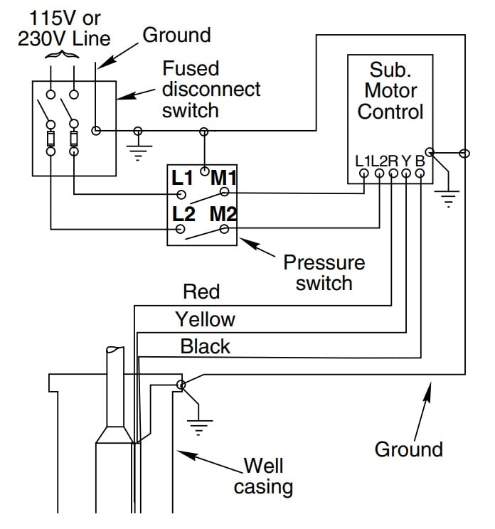
Well pump wiring diagram. In most cases if the leads are the same color then the polarity does not matter but check this with the installation sheet and wiring diagram. Each component ought to be placed and linked to different parts in specific way. It shows the components of the circuit as streamlined shapes and also the power and also signal links in between the devices. All well pumps come with a wiring diagram which provide specific instructions for your specific pump. A submersible pump can be either two or three wire regardless of the voltage coming from the. Collection of 3 wire submersible pump wiring diagram.
Wellborn collection of well pump pressure switch wiring diagram. 240 volt well pump wiring diagram 240 volt well pump wiring diagram every electrical arrangement is composed of various distinct pieces. It shows the elements of the circuit as simplified forms and also the power as well as signal links between the devices. Otherwise the structure will not function as it ought to be. The main breaker panel should have a wiring schedule handwritten inside the front door panel. A very first look at a circuit layout could be complicated however if you can review a subway map you could read schematics.
Submersible well pump wiring diagrams start at the breaker panel. A wiring diagram is a streamlined standard photographic representation of an electric circuit. Wiring a pressure switch is simply breaking the circuit power through the pressure switch contacts. Determine number of wires. 2 wire submersible well pump wiring diagram a newbie s overview of circuit diagrams.
Gallery of Well Pump Wiring Diagram