You can add it to a pick list that can be printed and taken to a western. The durable poly blade provides a slick surface for enhanced snow rolling action and a maintenance free surface.

Minute Mount Plow Wiring Diagram Honda 2012 Rmnddesign Nl
Western mvp v plow wiring diagram. Our easy to use exploded parts diagrams will help you quickly find the parts and components you need for your current snow plow models. Headlamp pair western part 61543 headlamp pair quantity. Mvp blade to straight blade adapter kit pn 66760k pin no. Ultramount mvp plus diagrams. After lowering blade and turning control off disconnect electrical connections. A wiring diagram is a streamlined standard pictorial representation of an electrical circuit.
Western part 61558 plow harness kit 12 pin u quantity. It shows the parts of the circuit as simplified forms as well as the power and also signal links between the tools. A wiring diagram is a simplified standard pictorial representation of an electrical circuit. Mvp 3 v plow. Plow diagrams blade t frame lift frame. Step 3 step 2 step 1 after seating plow horns in receiver brackets pull handle up.
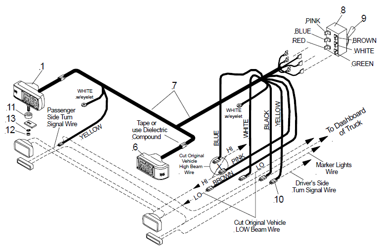
Electrical diagrams isolation module controllers plow side electrical 2 plug isolation module nighthawk headlamps. Assortment of western snowplow wiring diagram. Assortment of western snow plow wiring diagram. Wire color control function 1redyellow 12v 2 s e v l a n v e e r g t h g i 2l 3orangeblack ground 4 brownred motor relay 5 light blue valve s3 1 s e v l wa o v l l e y e t i h 6w pin no. Repeat steps 2 and 3 on other side of plow. Western part 61543 headlamp pair 39820 35838.
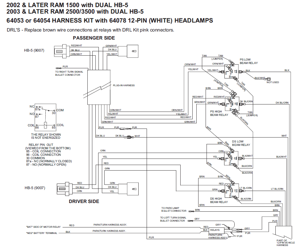
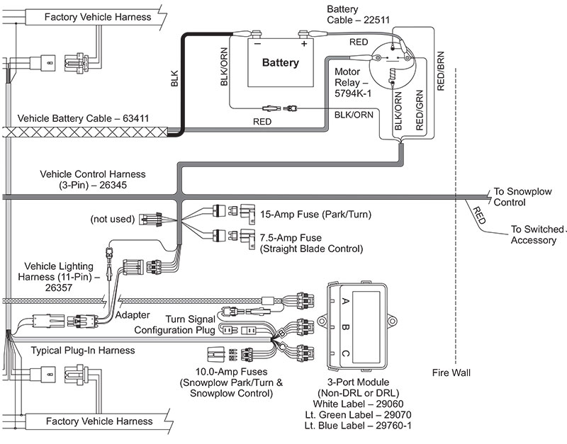
2 plug relay system wiring harness components diagram. Pull and hold lock pin out. Hydraulic diagrams hydraulic unit hoses lift ram angle ram. Then rotate handle up and release lock pin. Shoe will lift off the ground. Mvpultramount w 3 plugs hydraulics electrical system controls.
The mvp plus v plow is available in 14 gauge powder coated steel or 14 high density polyethylene in 7 6 8 6 and 9 6 widths. Parts diagrampdf installation instructionspdf mvp plus ultramount w 2 plugs fleetflex hydraulics electrical system controls. It shows the components of the circuit as streamlined forms and the power and signal links in between the gadgets. Parts diagrampdf installation instructionspdf mvp plus ultramount 2 w 2 plugs fleetflex hydraulics electrical. Solenoid control wire color only 1white 2green 3brown 4black 5blue 6red pin no. Mvp plus mvp 3 v plow.
Gallery of Western Mvp V Plow Wiring Diagram