Attach spreader to mount frame with a 58 x 1 34 bolt and locknut through top hole in spreader angle on each. October 20 2019 by larry a.
31 Western Snow Plow Controller Wiring Diagram Wiring
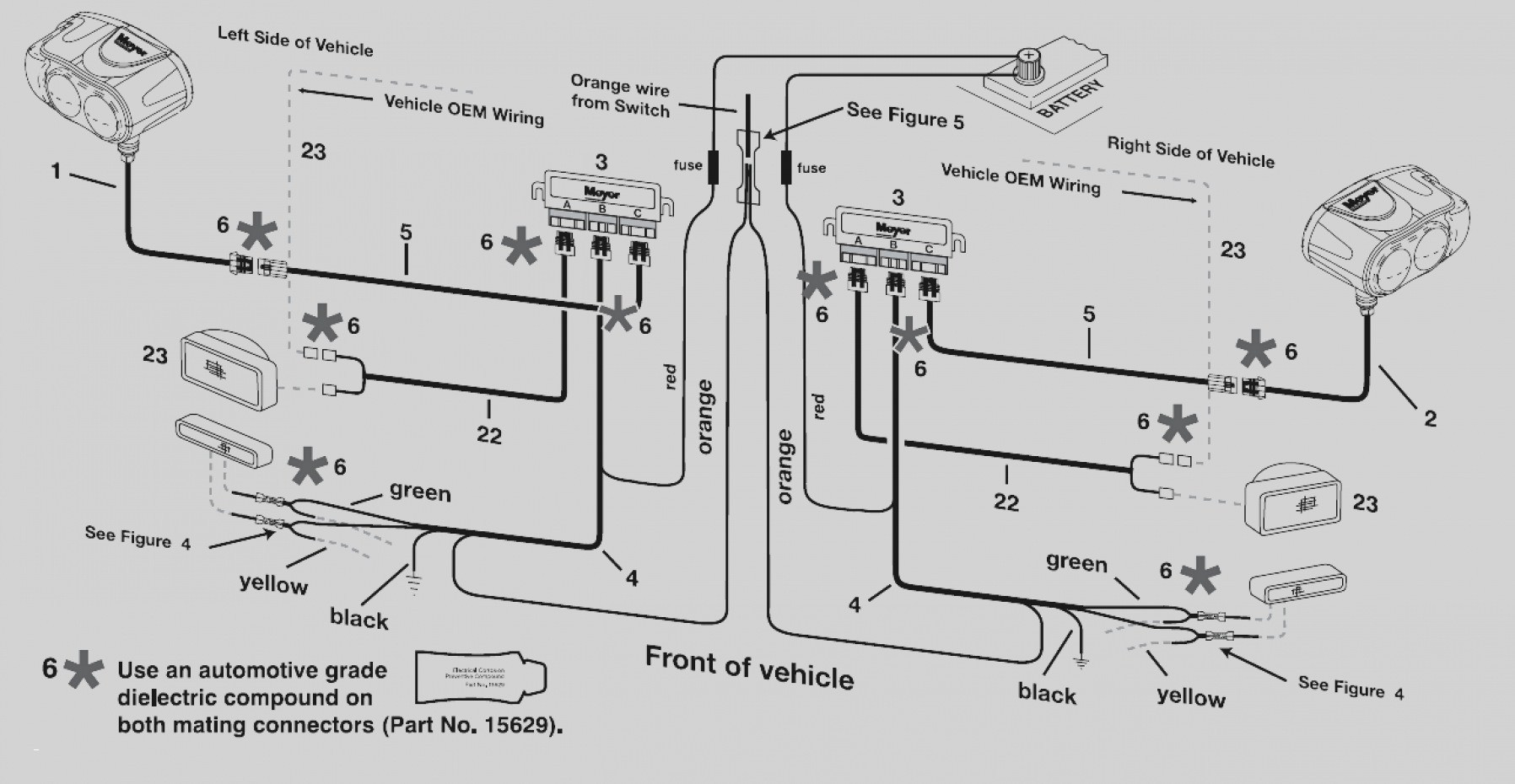
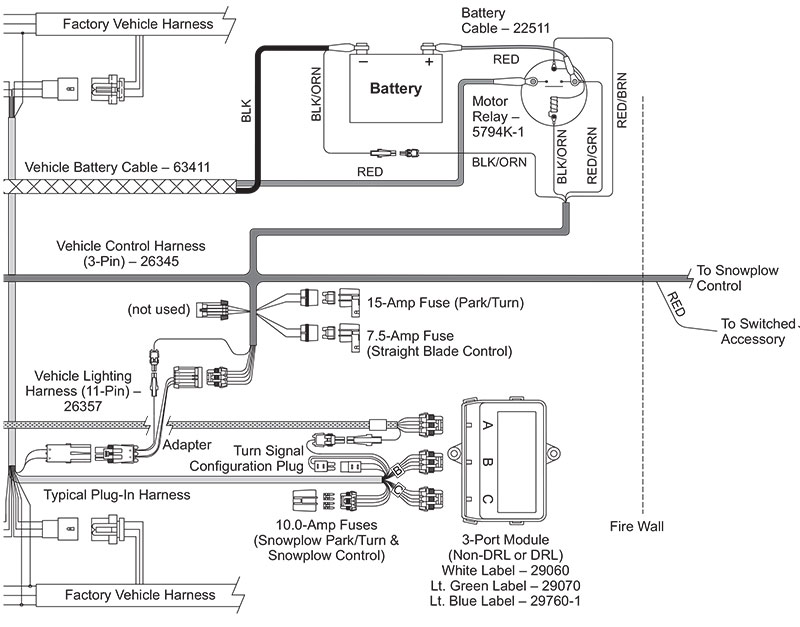
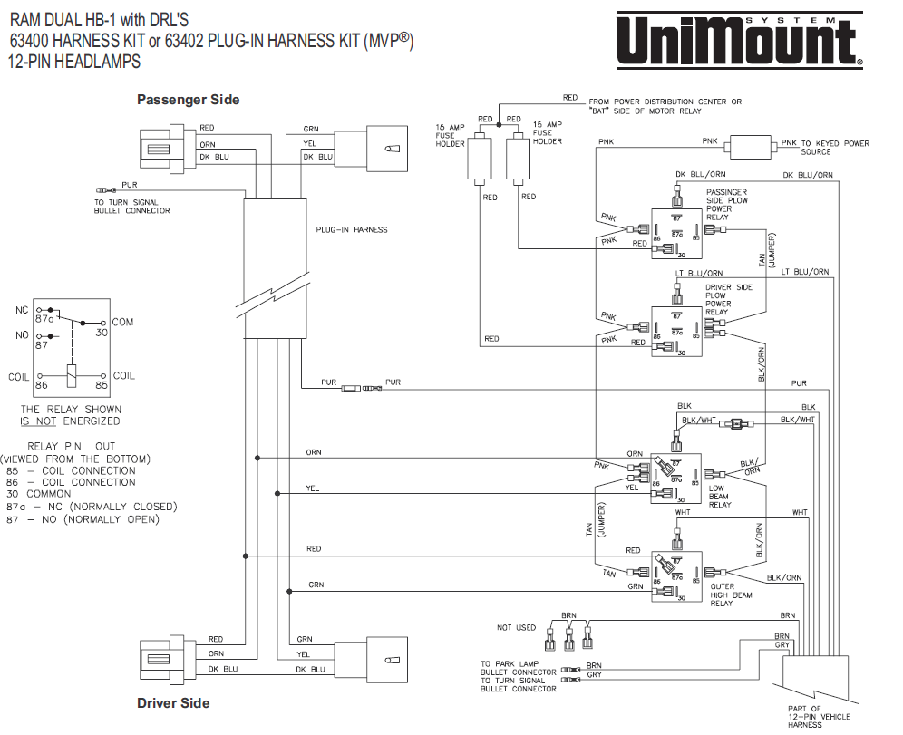
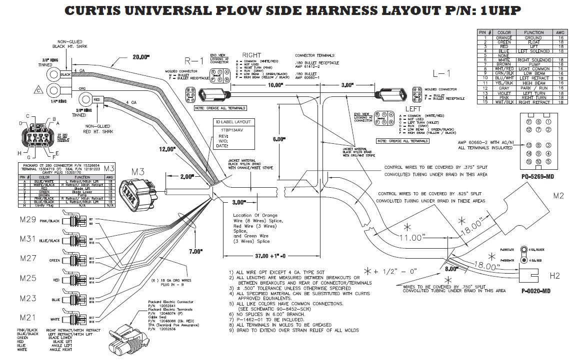
Western snow plow wiring diagram. Final coupling lug hole center to level surface distance should be 9 12 to 10 12 with plow attached and resting on the level surface. Straight plow hts standard midweight pro plow pro plow series 2 pro plus v plow mvp plus mvp 3 wide outprodigy wide out gen 22018 wide out xl wide out 2017 prodigy. When weight of plow is added. Western pro snow plow install on dads 04 silverado 2500hd duramax duration. Although intended primarily as a diagnostic tool for headlamp systems the hydraulic system circuitry is also included to show the complete electrical system. Western mvp3 truck side wiring install on my 2002 silverado duration.
A wiring diagram is a simplified standard pictorial representation of an electrical circuit. Western snow plow solenoid wiring diagram whats wiring diagram. Assortment of western snowplow wiring diagram. Parts lists installation instructions. A wiring diagram usually offers info regarding the family member position and also arrangement of tools and terminals on the tools to assist in structure or servicing the tool. Plow transfer quote request.
It contains schematics diagrams and charts which supply information for the various types of vehicle and plow headlamp systems. A wiring diagram is a kind of schematic which makes use of abstract photographic icons to show all the affiliations of components in a system. It shows the parts of the circuit as simplified forms as well as the power and also signal links between the tools. Western products has been leading the industry by providing quality snow plows ice control equipment including tailgate spreaders and snow plow accessories. Search parts service documentation. Assortment of western snow plow wiring diagram.
Diagnosis and repair of western snowplow electrical systems. A wiring diagram is a streamlined standard pictorial representation of an electrical circuit. It shows the components of the circuit as streamlined forms and the power and signal links in between the gadgets. See coupling lug height check near end of these instructions 2. A wiring diagram normally provides details about the family member placement and plan of devices and terminals on the tools to assist in structure or servicing the device.
Gallery of Western Snow Plow Wiring Diagram