Wire range alcu cat. Basics 11 mov schematic with block included basics 12 12 208 vac panel diagram.
Asi Free Full Text Survey Of Smart Grid Concepts And
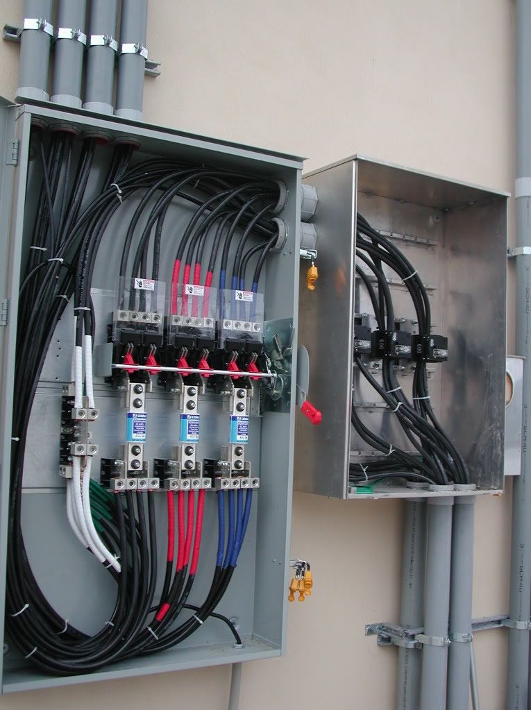
Wiring diagram panel mdp. Basics 13 valve limit switch legend. Plenty of excess wire is pulled into the panel to allow for connections to be made anywhere in the box. Special cabinets can be provided at an additional charge. Our prof provided us a guide in making a 3 phase electrical layout but he didnt explain anything. Standard panelboard boxes are supplied without knockouts blank endwalls. A wiring diagram is a streamlined standard pictorial depiction of an electric circuit.
What exactly does that mean thanks. For outside dimensions add 025 inch 64 mm. It shows the components of the circuit as simplified shapes and the power as well as signal connections between the devices. The box dimensions shown are inside dimensions. Basics 14 aov schematic with block included basics 15 wiring or connection. Wire range cu only 125a mla1 6 350 mlt1 4 300 mlr1 4 350 225a mla2 10 250 mlt2 20 500 mlr2 10 600.
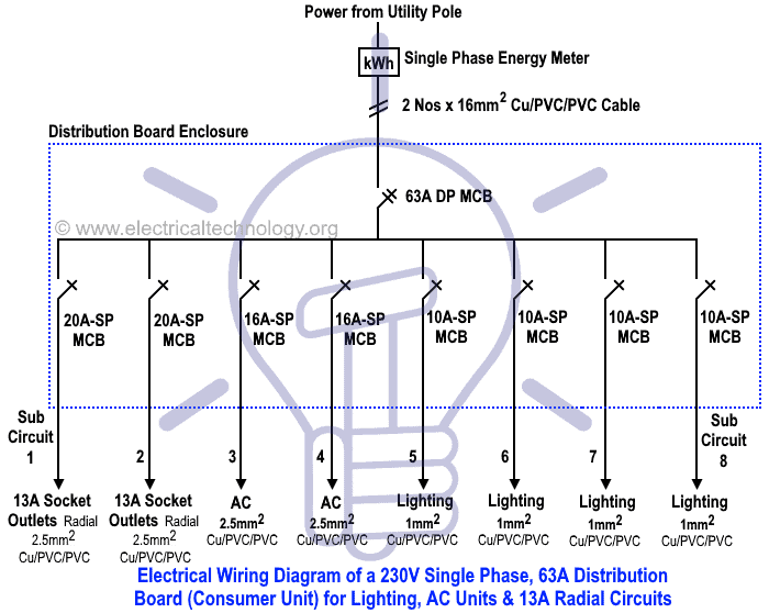
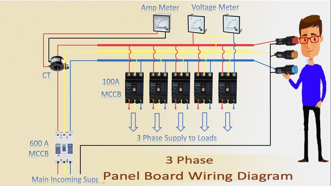
The lower voltage is then used to supply power to the left and right rails of the ladder below. In the layouts schedule of loads the loads are divided into two. Tentang sistem dan jenis panel distribusi listrik mvmdb lvmdb kami menerima pembuatan panel mdp sdp panel control motor panel inverter dan panel plc. Figure 1 a motor controller schematic. Control panel programming guide contains programming instructions for use with the model xr150xr550 series control panels when using the xr150xr550 series panel for any listing organizations approved methods refer to this manual and the xr150 xr550 series installation guide lt 1233. A single line diagram illustrating the functionality of the mdp relay is shown on the following page.
A typical wiring diagram is shown in figure 12. The edp and mdp. Ez trim the ez box and ez trim are provided. Basics 9 416 kv pump schematic. Current ranges nominal current in inverse time unit is instantaneous unit phase ground 5 a 15 to 1325 a 15 to 13125 a 1 to 31 is. In most panels the main breaker is a large 240 volt circuit breaker that is located at the top of the panel.
The contacts m will be controlled by the coil mthe output of the motor starter goes to a three phase ac motor. The electrician now bends the two black service wires for easy installation to the main breaker. Typical wiring diagram on page 13. Basics 7 416 kv 3 line diagram. Basics 8 aov elementary block diagram. Include wiring gutters with proper wire bending space.
Basics 10 480 v pump schematic. Wire range alcu cat. Power is supplied by connecting a step down transformer to the control electronics by connecting to phases l2 and l3.
Gallery of Wiring Diagram Panel Mdp