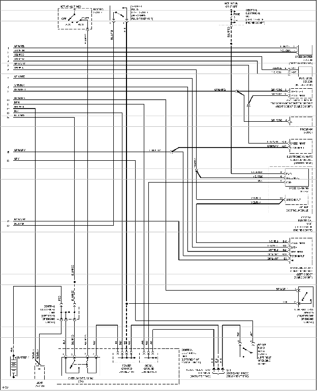
Yazaki tachometer wiring diagram wiring diagram is a simplified adequate pictorial representation of an electrical circuit. Note all wiring checks out ok all the way the the tach.
Supplier Yazaki Europe
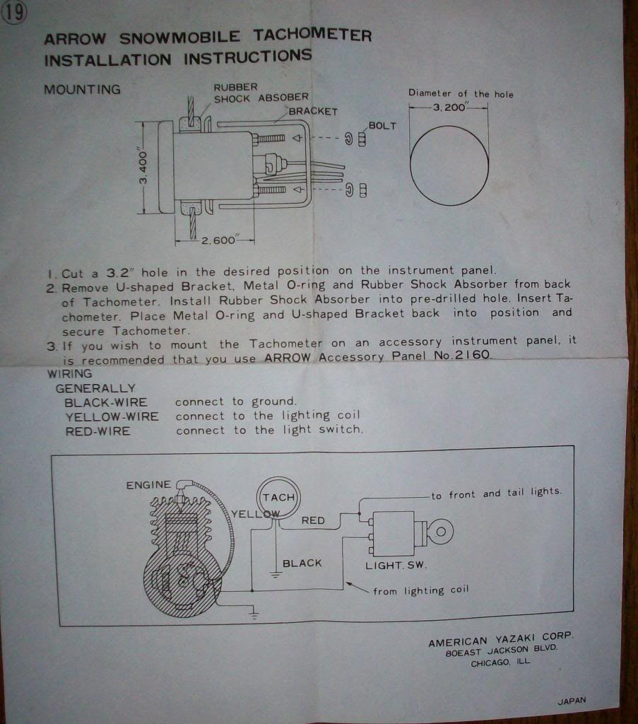
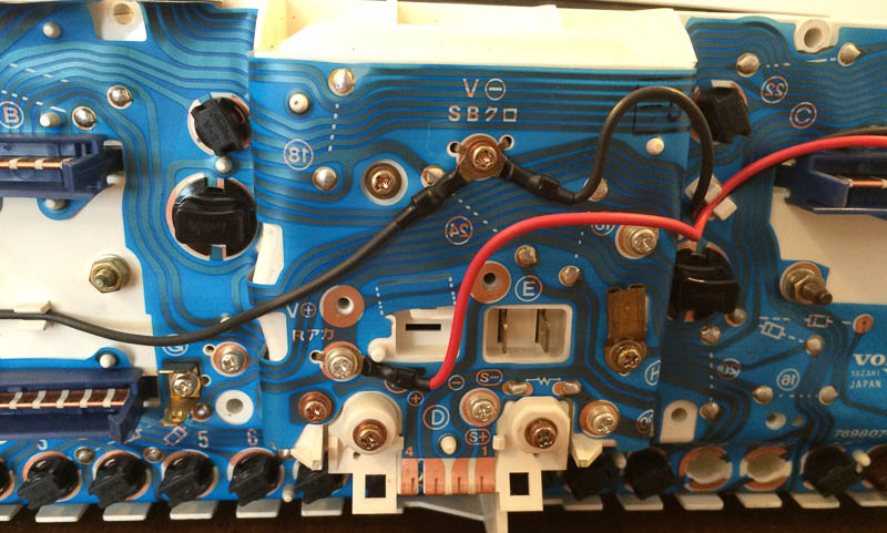
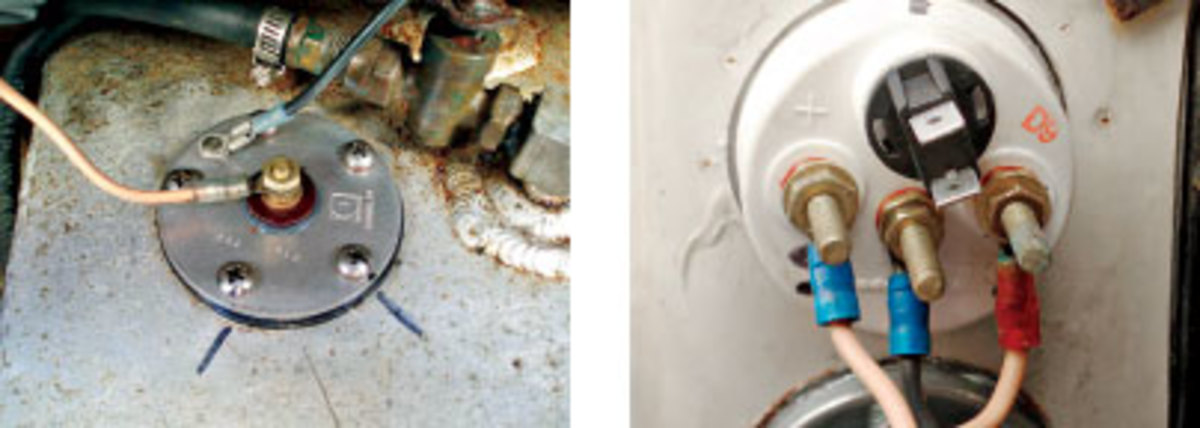
Yazaki tachometer wiring diagram. Connect a wire from pin 5 to a constant 12 or 24 volt source. One such source can always be found where the battery is attached to the metal frame of the vehicle. Wire to a junction and attach the wire from pin 4 at this junction ie. Its weird but im thinking it has this adapter that may be incorrectly connected to the tach. Variety of yamaha outboard tachometer wiring diagram. Circuit diagram the circuit is based on the industry standard cd14538 chip which features two.
It shows the components of the circuit as simplified shapes and the facility and signal links together with the devices. Cost of the electronic parts was around 56 at the time of writing this article. A wiring diagram is a simplified standard photographic representation of an electric circuit. Their clear easy to understand displays provide drivers with safety and security and their stylish design adds pleasure to the driving experience. Traced all wiring and connectors for continuity and all is good. Attach the wire from pin 3 to a ground negative source.
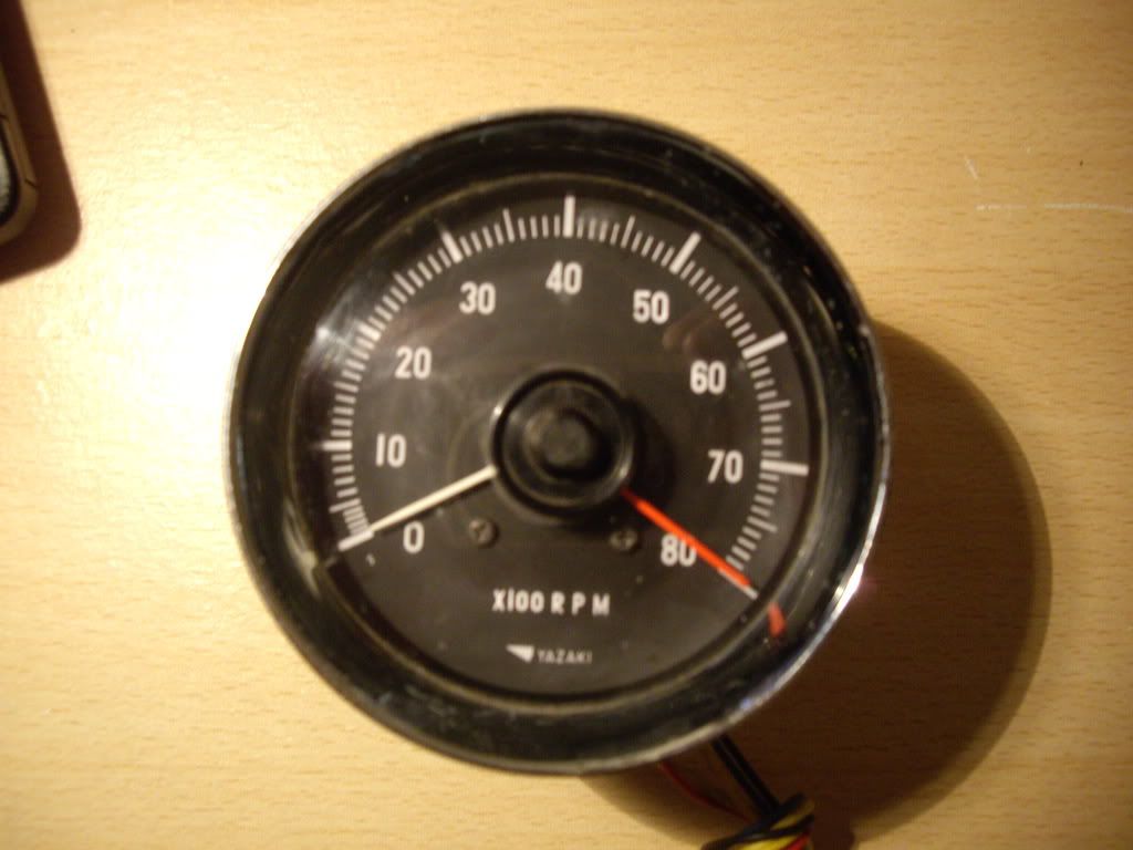
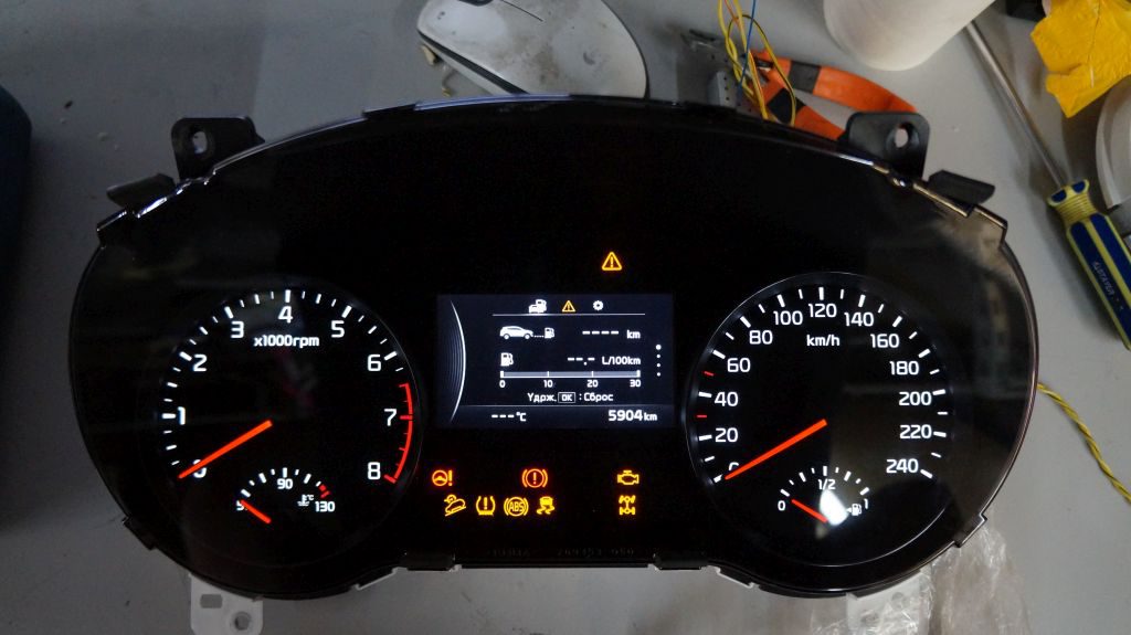
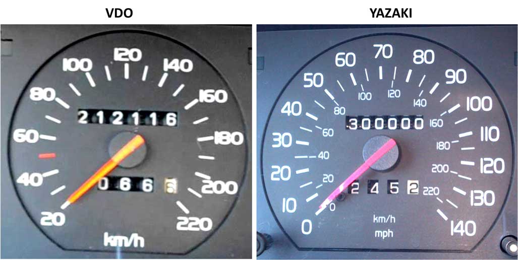
Yazaki made meters can be found in many of the cars on the road in japan and around the world. The circuit is easy to assemble and based on standard wire through electronic parts which should be easily available via electronic stores and mailorders. 1 this wiring diagram booklet is designed for use with the rev speed meter aa please be sure to read the instruction manual for the. I can bypass the wiring and connect directly to the tach and sender reads correctly. Identifying yazaki or vdo type instrument cluster. Jun 23 the following meter wiring diagrams provide details of the wiring of typically receive a single element single meter for connection to a.
They serve as the interface between people and their cars. Refer to diagram d. It reveals the elements of the circuit as simplified forms as well as the power and signal connections in between the tools.
Gallery of Yazaki Tachometer Wiring Diagram