Emergency lighting testing on the dali network. Smaller systems mlsuca up to 6 x rb2000 bus power supply up to 127 intelligent lcms per rb2000.

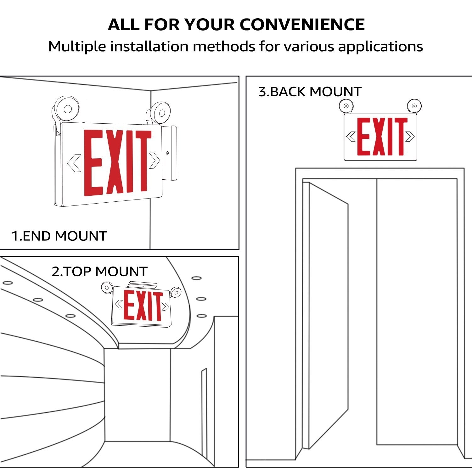
Wired Installation Ektor Uk
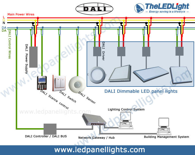
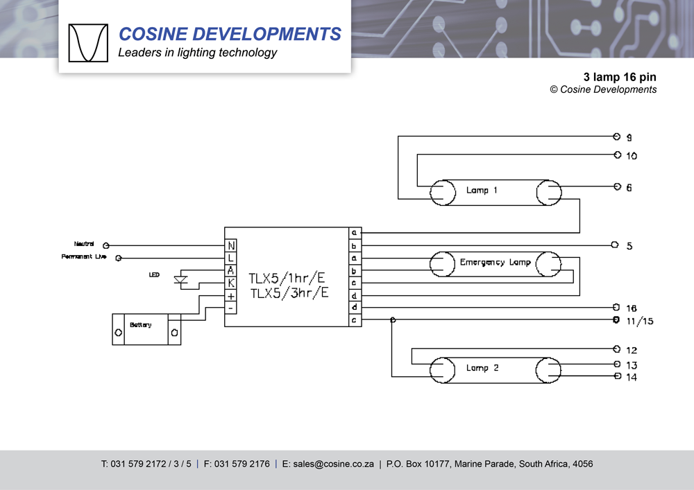
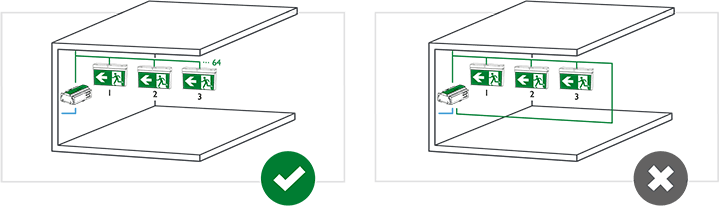
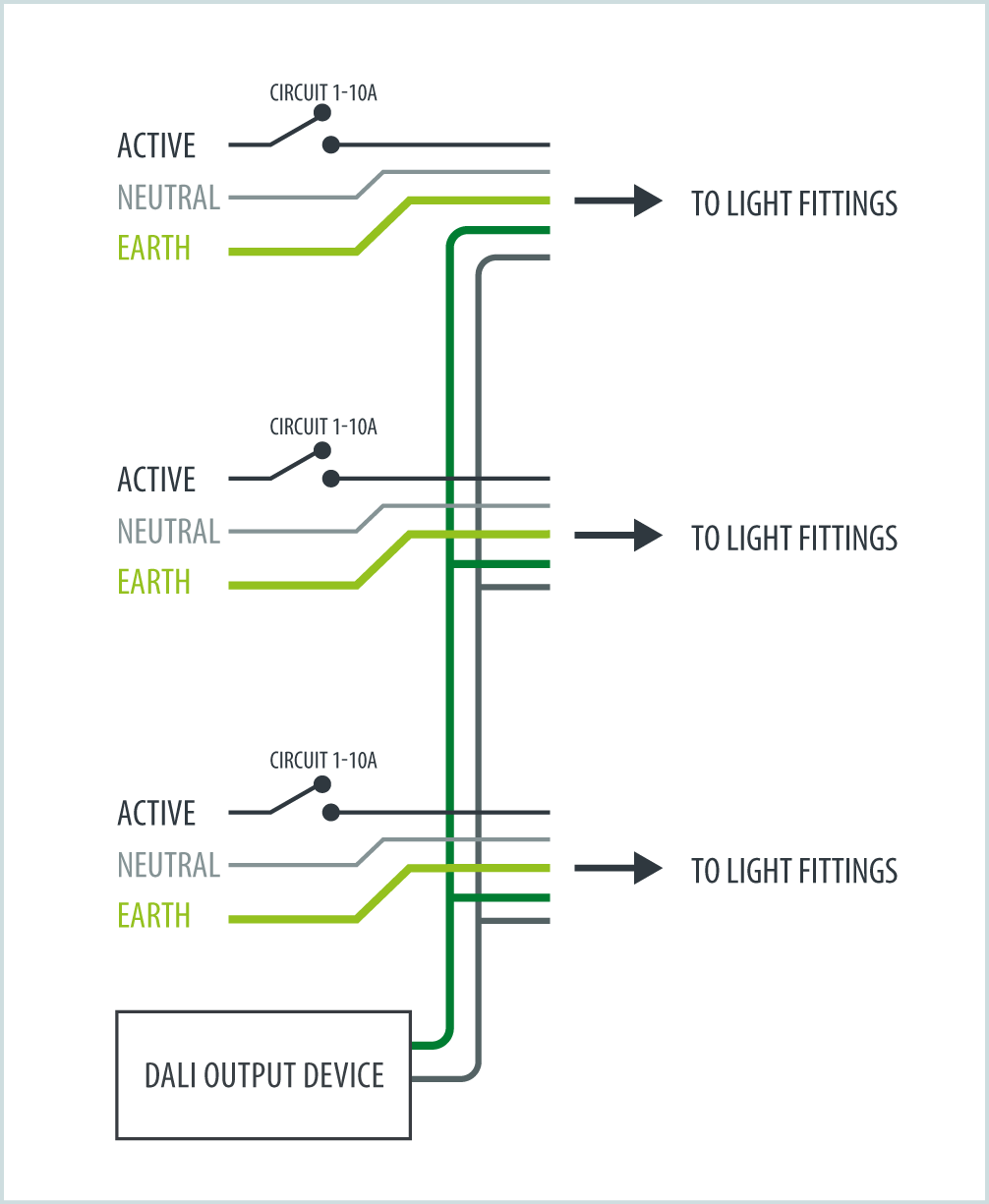
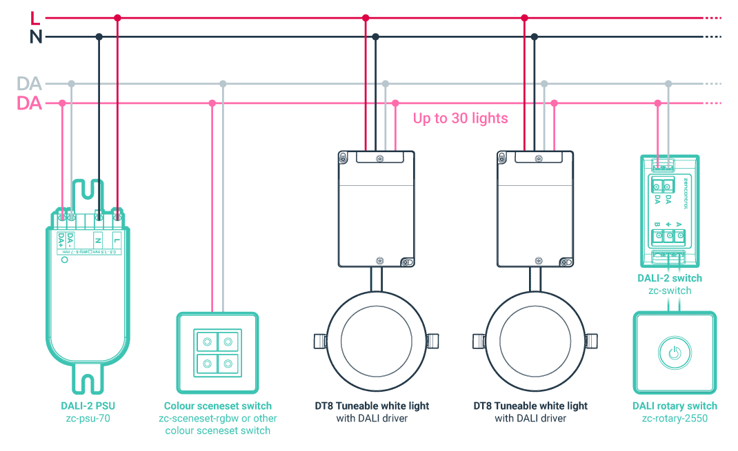
Dali emergency lighting wiring diagram. The unique method of dali wiring also makes it possible for emergency lighting to run on the dali network. Led drivers and ballasts are connected using class 1 inside the conduit or class 2 outside the conduit wiring to make up a loop of no more than 64 led drivers or ballasts. The nda3 is the popular choice for converting most standard led luminaires and arrays containing from 2 to 20 leds in series whilst the nda380 extends the range by converting from 2 to 30 leds in series. Collection of dali lighting control wiring diagram. Typical dali layout fluorescent light emergency light downlight dali network boardroom showroom. It shows the components of the circuit as simplified shapes and also the power and also signal connections in between the gadgets.
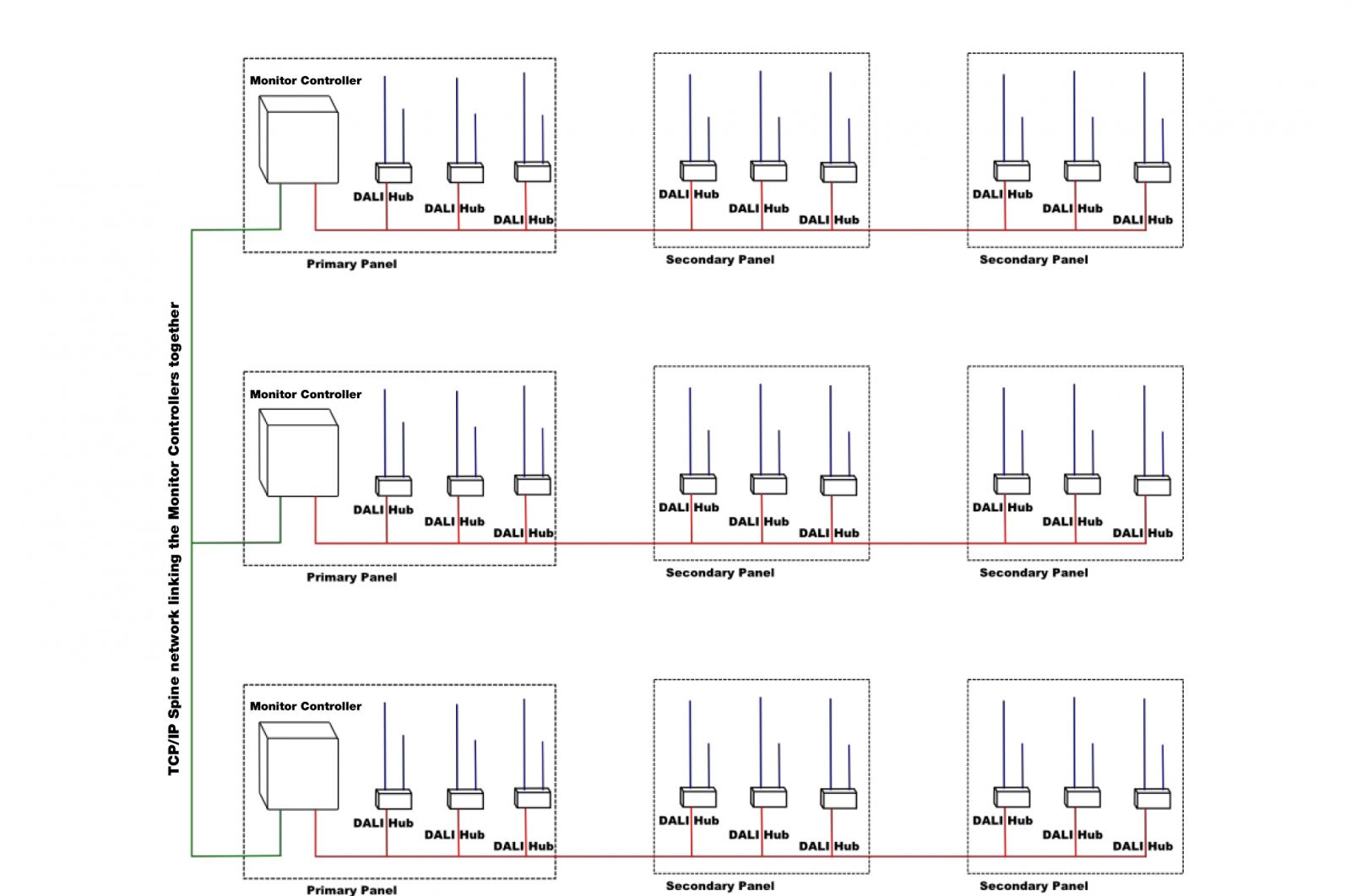
The liteplan nda3 dali self test emergency lighting modules are designed to convert a wide range of led types with two versions. Each is given an address in the dali system and the loop is connected to a dali control device. Alongside the mains wiring dali emergency lighting testingbems interface by adding an mlsuca or mlsucb system controllerinterface you can automate the testing of dali emergency luminaires andor interface to bems or hvac via bacnet. Dali dali dali wiring consists of 2 control wires with a current limited power supply supplying a maximum current of 250ma. This is done with a computer system. Rather several must be linked together to create a.
Moreover these dali compatible emergency fittings can be scheduled for automatic testing and reporting. Dali wiring up to 64 dali lamps per network 16 groups within each network and 16 scenes per group diagram 2. A wiring diagram is a streamlined conventional pictorial representation of an electric circuit. One individual network isnt enough to cover an entire building.
Gallery of Dali Emergency Lighting Wiring Diagram