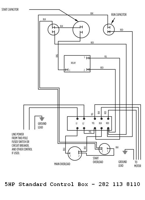
It shows the components of the circuit as simplified shapes and the talent and signal links in the midst of the devices. Single phase submersible pump control box wiring diagram 3 wire submersible pump wiring diagram in submersible pump control box we use a capacitor a resit able thermal overload and dpst switch double pole single throw.

Water Pump Wiring Troubleshooting Amp Repair Pump Wiring Diagrams
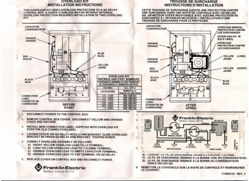
Franklin electric submersible pump wiring diagram. Otherwise the structure wont work as it. The wiring connection of submersible pump control box is very simple. All 3 wire submersible pumps from 13 up to 1 hp utilize a qd control box to start the pump. Here is the complete guide step by step. Franklin electric control box wiring diagram franklin electric control box wiring diagram franklin electric qd control box wiring diagram franklin electric well pump control box wiring diagram every electrical arrangement consists of various distinct pieces. Franklin installation information is available from pump manufacturers and distributors and directly from franklin electric.
In this video chris shows you how to wire the franklin electric qd control box. Each part ought to be set and connected with other parts in specific manner. 12 franklin electric motor wiring diagramfranklin electric 12 hp motor wiring diagram franklin electric 1081 pool motor wiring diagram franklin electric 34 hp motor wiring diagram franklin electric motor wiring diagram franklin electric motor wiring schematic franklin electric submersible motor control wiring diagram franklin electric submersible motor wiring diagramwiring diagram. Call franklin toll free 800 348 2420 for information. Local electrical codes and within franklin electric recommendations may result in electrical shock or fire hazard unsatisfactory performance and equipment failure. Submersible well pump wiring diagram wiring diagram is a simplified all right pictorial representation of an electrical circuit.
Gallery of Franklin Electric Submersible Pump Wiring Diagram