The gem gr2 double motor boat lift remote is a standard line of controls equipped with a 30 amp control relay. You have a gr2 dont use motor 2 wires cap them off.

32 Gem Remotes Wiring Diagram Wiring Diagram List
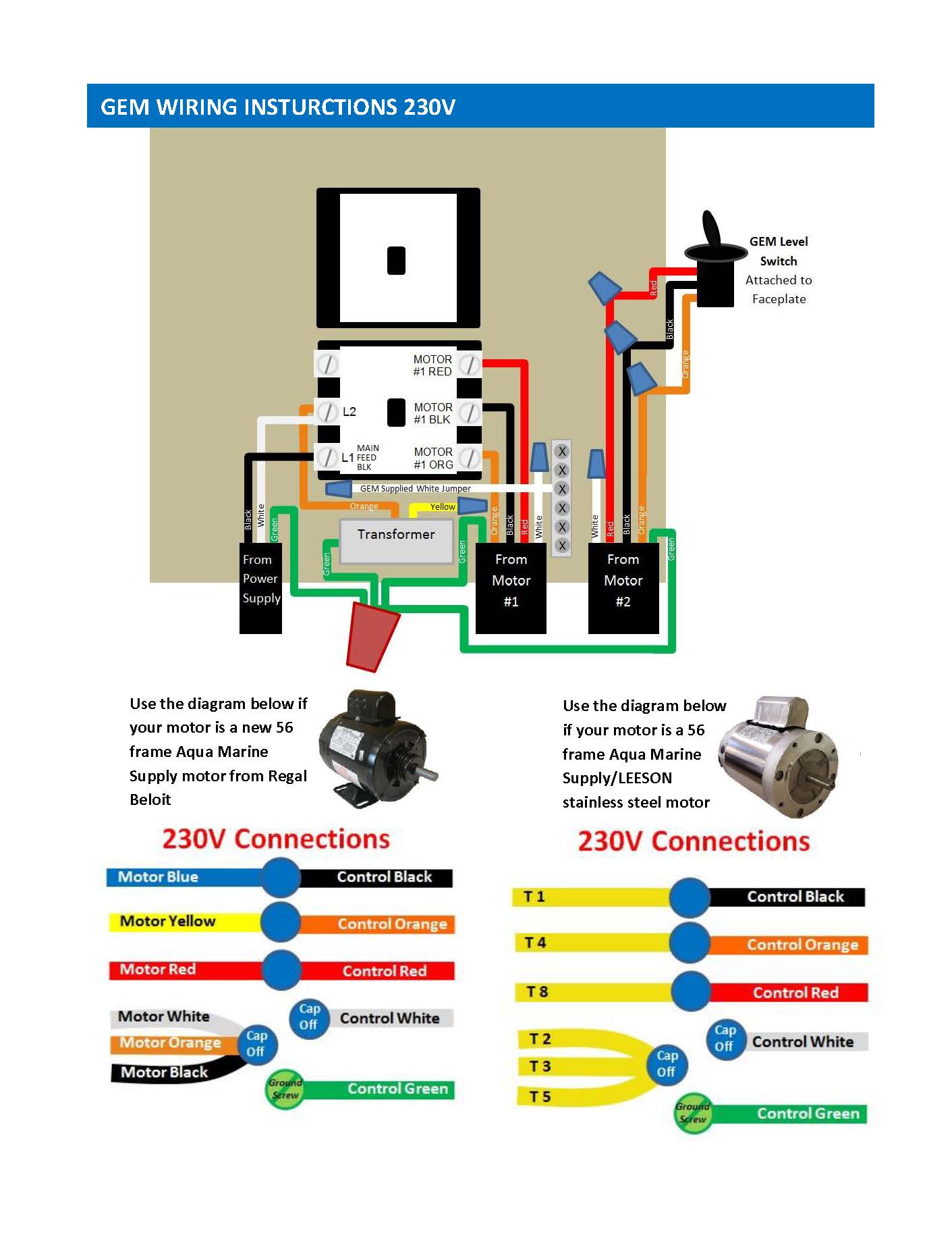
Gem remotes gr2 wiring diagram. Cap off the gem white motor wires. Use the motor wire diagrams below. Based in naples fla gem continues to perfect a remote control system which increases the safety and convenience of your boatlifts davits hoists or personal watercraft ramps. Includes floating water resistant miniature remote control transmitter. These wires are not used at 230vac. Ffc and etl listed and meets all federal requirements.
Collection of gem remotes wiring diagram. Gem remotes has been manufacturing boatlift controls since 1985. We infuse all of our products with quality features you will come to expect when you think of us gem remotes. Assortment of gem remote wiring diagram. A wiring diagram is a streamlined standard photographic depiction of an electrical circuit. Please use motor label for proper size and code compliance.
Naples fl 34113 phone number. Consult the gem remotes installation instructions for more detail. You may follow these instructions if you do not have a neutral. A wiring diagram is a streamlined traditional pictorial depiction of an electrical circuit. 2010 white wires and red wire nut neutral drawing. Based in naples fla gem continues to perfect a remote control system which increases the safety and convenience of your boatlifts davits hoists or personal watercraft ramps.
230 vac no neutral. Drum switch orange might be pre wired to motor black. Connect green or bare wires to green wire on the transformer. Controls two boat lift motors on one lift at the same time. To confirm andor change motor wiring open motor covers and configure motor winding wires as shown below. 2011 to june 2012 gem wiring diagram dec.
Gem remotes 356 capri blvd. 2012 to june 2015 added regal beloit motor and has old gfi info gem wiring diagram nov. Wiring the motors and the gem unit at 230vac. It reveals the components of the circuit as streamlined shapes as well as the power and also signal links between the gadgets. Turn off power at the circuit breaker. Inspect wires inside each motor to ensure proper wire connection.
A wiring diagram is a streamlined standard photographic depiction of an electrical circuit. Wiring from gem unit to change motor direction switch motor black motor red wires. We recommend that you wire your gem remote at 230 vac with a neutral. 2011 first neutral bar drawings gem wiring diagram jan. Recommended wire size for installation of your gem controller 1 phase75c copper wire of motorsmotor hp 120 volt ac main feed 240 volt ac main feed breakers size is our recommendation. Use of other wiring directions could result in damage to your gem unit andor the motor.
Collection of gem remotes wiring diagram. Read the gem remotes owners manual for operating instructions. Gem wiring diagram nov. It shows the components of the circuit as streamlined forms as well as the power and also signal links in between the gadgets.
Gallery of Gem Remotes Gr2 Wiring Diagram