Input output input output in case two or more connectors are connectedtothesamedevicemarkings indicating the same connectors are connected by a broken line. Most symbols used on a wiring diagram look like abstract versions of the real objects they represent.

Simple To Read Wiring Diagram For A Boat Boat Wiring
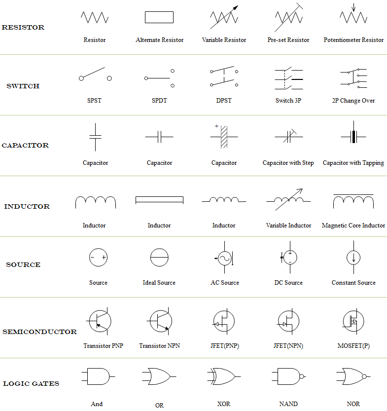
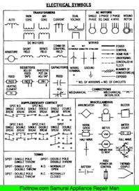
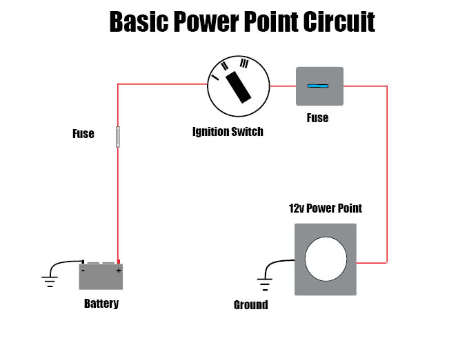
How to read a wiring diagram. Switch manual or controlled load light bulb motor etc ground return path to negative side battery. A typical basic circuit consists of five important parts. All wires are then identified using a color code and a number but well see more about that later in this article. On very rare occasions a component may be placed at 45 degrees but only for a very good reason. Learn the meanings of the basic circuit symbols and choose the correct ones to use. Use the right symbols.
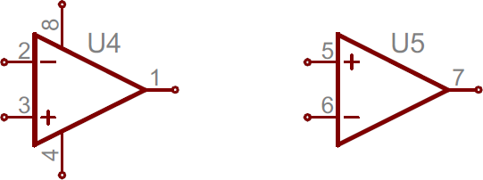
Take care of every detail. How to read the wiring diagrams how to read circuit diagrams a 5 indicates inputoutput tofrom controlunitcurrentflowdirection. Most wire diagrams will have a legend or key just like a road map explaining wire color codes or any other special information needed to read the diagram. Power supply positive from battery fuse. When unconnected lines are shown crossing youll see a line hop. Next you see a label 3011.
On a diagram theres no visual difference between wire gauges and materials. This is the wire number of the wire that connects the switch to the relay and it should be labeled as such on each end of the wire and in any junctions that connects it. That way when someone looks at the switch they know exactly where to find it in the wiring diagram. In electrical diagrams every straight black line represents a wire. Below is a list of color codes commonly used in wire diagrams to portray wire color and their purposes. In some cases a diagonal line may be used which is placed at 45 degrees.
A good wiring diagram needs to be technically correct and clear to read. For example a switch will be a break in the line with a line at an angle to the wire much like a light switch you can flip on and off. Component symbols in a circuit diagram are usually placed horizontally or vertically. For example the diagram should show the. Physically parts are connected by wires in the diagrams you will see black lines going from one part to the next. This means that you connect them with a wire when the black lines cross in a diagram there are ways of telling whether or not the wires should be connected to each other as shown below.
Tips to draw good looking wiring diagrams. Wires or lines in circuit diagrams are usually horizontal or vertical. Indicates current flow downward or upwardascontrolledbythecontrolunit. The switch would be labeled 301sw1 in the field.
Gallery of How To Read A Wiring Diagram