It reveals the components of the circuit as streamlined shapes and the power and also signal connections in between the devices. Itc 100 controller pdf manual download.

Cdfe5e9 Pid Temperature Control Wiring Diagram Wiring Resources
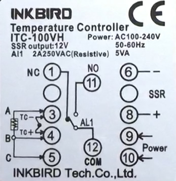
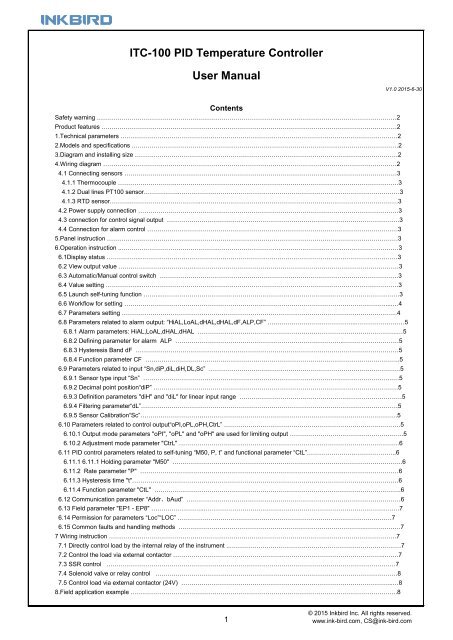
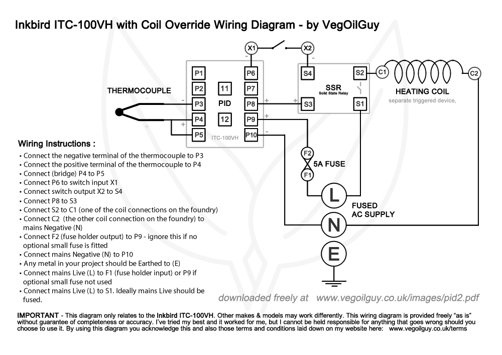
Inkbird pid wiring diagram. The power source is the mains in your neck of the woods. View and download inkbird itc 100 user manual online. Pid wiring diagram wiring diagram for the inkbird itc 100vh pid. Support multiple thermocouples and resistance sensors k s wre t e j b n cu50 pt100 wide controlling range. Other makes and models will need to be wired differently. 501300 k sensor high accuracy of displaying and controlling 01 accuracy of measurement 02fs.
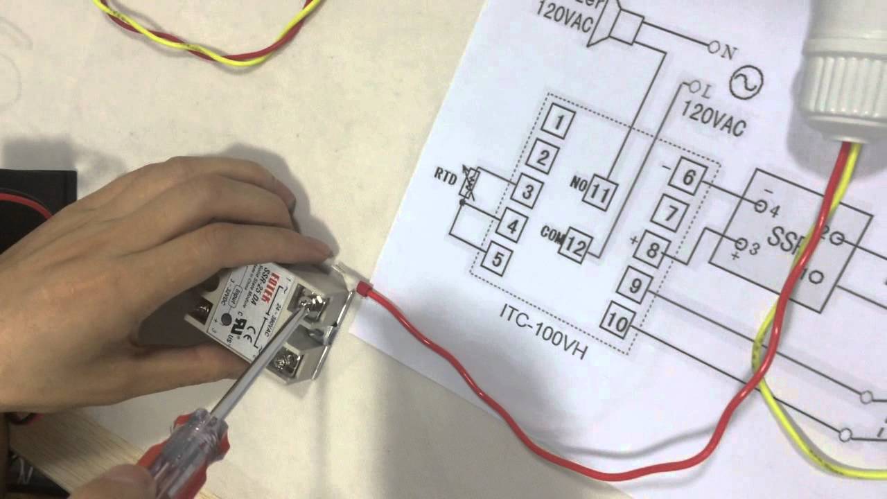
Warrants this thermostat for one years from the date of purchase when operated under normal condition by the original purchaser not transferable against defects caused by inkbirds workmanship or materials. Here you can download our latest user manuals drivers and other supporting materials from inkbird support department. If you are using a 3 wire sensor then it connects to terminals 3 4 and 5. Lets start with the temperature sensor. How to wire the inkbird itc100vh pid with a pt100 thermocouple ideal accurate temperature control solution for powder coating ovens when curing powder coating work it is beneficial to have an. In the instruction manual for your pid and possibly on a sticker on the case will be a wiring diagram like the one above.
In my case im in the uk and the standard mains power is 230 volts ac. A wiring diagram is a simplified standard photographic representation of an electric circuit. If you know how to translate it wiring everything up is quite simple. Please remember this diagram relates only to the inkbird itc 100vh pid. Collection of pid temperature controller wiring diagram. This warranty is limited to the repair or replacement at inkbirds discretion of all or part of the thermostat.
Gallery of Inkbird Pid Wiring Diagram