Drawing number description unit size. L120 ncu wiring diagram title of each drawing downloads the file.

Limitorque Accutronix Mx Electronic Valve Actuator User
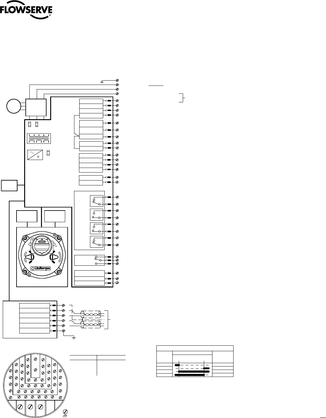
Limitorque wiring diagram. 3ph optional potentiometer. A wiring diagram is a simple visual representation of the physical connections and physical layout of your electrical system or circuit. It shows how a electrical wires are interconnected and will also show where fixtures and components may be attached to the system. Limitorque actuation systems standard control features 3 protection features 4 optional control features 5 fieldbus protocols 6 monitoring and diagnostic facilities 7 remote facilities 8 auxiliary power supply 8 standard wiring diagram 9 optional features wiring diagrams 10 ddc 100 foundation fieldbus and profibus network wiring diagram 11. Limitorque l120 wiring diagram sample architectural wiring representations show the approximate areas and affiliations of receptacles illumination as well as long term electric solutions in a structure. Interconnecting wire routes might be revealed around where particular receptacles or fixtures should be on a typical circuit.
L120 ncu wiring diagram share. Mxa wiring diagrams single phase. Limitorque l120 wiring diagram what is a wiring diagram. Limitorque wiring diagram web21 flowserve flowcontrol limitorque lmentb2300 02 pdfcurrent wiring diagram is located within the terminal compartment the following control features are included in the basic speci cation for optional features please refer to section 2 3 optional control features limitorque wiring diagram by categorylimitorque wiring diagrams are listed for most standard and optional electrical electronic configurations of currently supported products if the drawing is not found. This information is located on the unit nameplate. Limitorque wiring diagrams are listed for most standard and optional electricalelectronic configurations of currently supported products.
L120 ncu wiring diagram.
Gallery of Limitorque Wiring Diagram