It shows the components of the circuit as simplified shapes and the capacity and signal friends together with the devices. Variety of mechanically held lighting contactor wiring diagram.

Square D 8903lo30v02
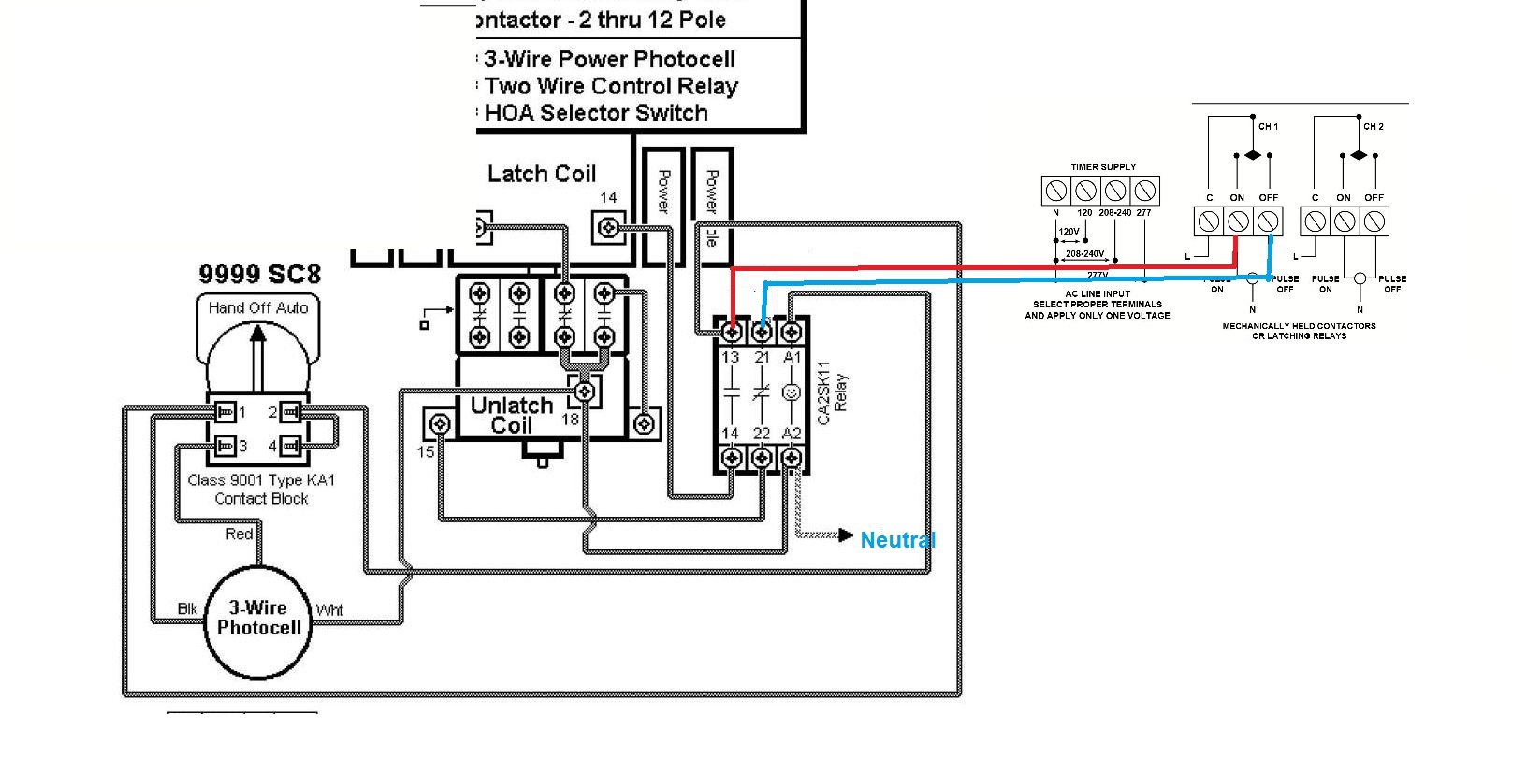
Mechanically held contactor wiring diagram. The coil for contactor operation. Electrically held to mechanical latch contactor retrofit instructions 5 1502 in001 en p xqh install the mechanically latched auxiliary contact assembly 1. February 16 2019 by larry a. Contactor as shown in figure 7. Square d 8903 lighting contactor wiring diagram square d 8903 lighting contactor wiring diagram at mechanically held throughout. It shows the elements of the circuit as simplified forms as well as the power and also signal connections in between the gadgets.
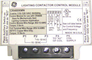
For mechanically held contactors remove all wires from the control module and remove the coil cover along with control module. Mechanically held lighting contactor wiring diagram. Wire the closing and trip coils to the mechanically latched auxiliary contact assembly as shown in the diagram below. Cr463m mechanically held contactors a mechanical latch with a 2 or 3 wire electronic control module delivers reliable performance and protection from such application abnormalities as line noise leakage currents from controller outputs or short repetitive commands burst from faulty controllers. Figure 6 auxiliary contact assembly layout 2. Square d mechanically held contactor wiring diagram wiring diagram is a simplified satisfactory pictorial representation of an electrical circuit.
Figure 7 table c 53 wiring coil terminal can accept wires from 18 awg to 14 awg either solid or stranded as single or combination of two wires. A wiring diagram is a simplified standard pictorial depiction of an electric circuit.
Gallery of Mechanically Held Contactor Wiring Diagram