Plc goc 35 input output wiring duration. How to follow an electrical panel wiring diagram duration.
Plc Digital Input And Digital Output Modules Plc Hardware
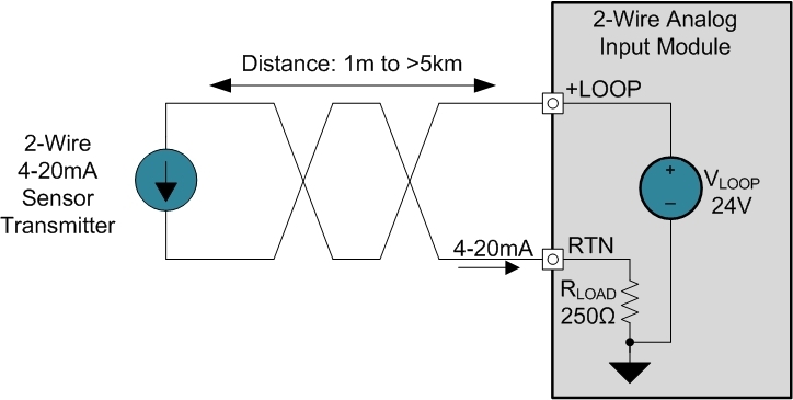
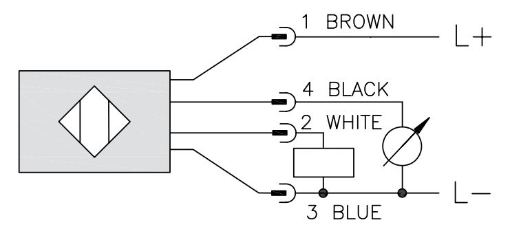
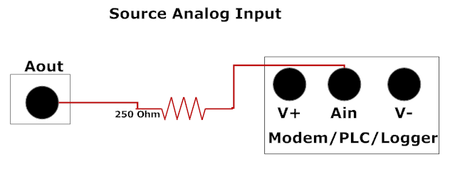
Plc analog input wiring diagram. The following is a wiring diagram of an open collector pnp sensor. In this tutorial i will cover wiring of the two most basic analog input signals. Plc analog input conversion formula plc tutorials for any unit conversion on any plc you can use four function math with the following for plc analog input conversion formula. In this article we are sharing the basic concepts of plc and dcs control systems wiring diagrams for digital input di digital output do analog input ai and analog output ao signals. Before you start wiring any plc analog module i highly recommend that you not only read the manual but also know what type of signal youre dealing with. You can select from five voltage or three current input ranges.
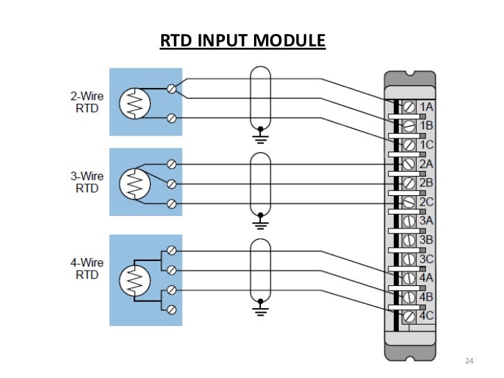
Wiring a plc analog input is a bit different depending on the type of signal. Each input can be configured as a current or voltage input with internal jumpers. When connecting to the plc the plc input acts as the load. Wiring of analog inputs. Plc wiring diagrams guide include the discrete signals wiring plc digital input modules wiring plc output modules wiring and basics of plc terminations. You will notice that the load appears between the 0v blue and switching wire black.
The analog input module senses up to 16 single ended or 8 differential analog inputs and converts them to a proportional four digit bcd or twelve bit binary value. The 0v blue will be attached to the common input and the switching wire black will be attached to the input number. Plc analog inputs and signals duration. Note that these diagrams are without a barrier or isolator fuses and surge protector for keeping it very simple and understandable.
Gallery of Plc Analog Input Wiring Diagram