As far as cameras power ptz data and wiring is concerned theyre. Assortment of ptz controller wiring diagram.

Ptz Controller Scc 1000 User S Manual
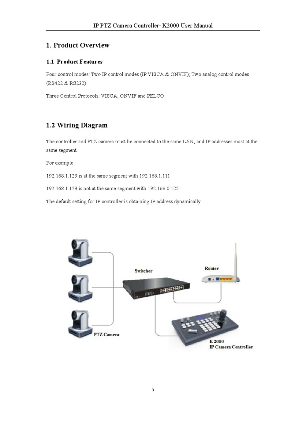
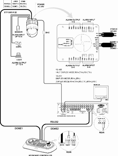
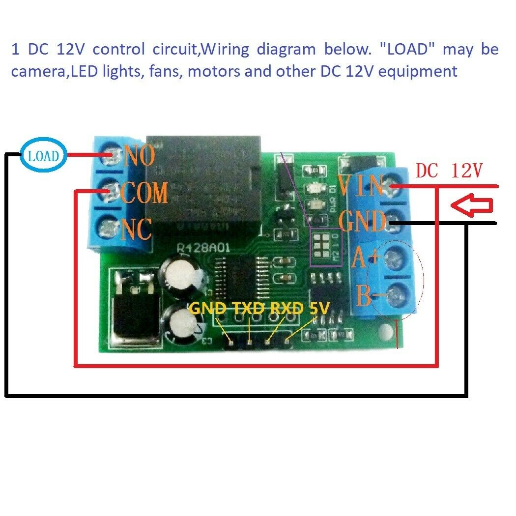
Ptz controller wiring diagram. A basic knowledge of electrical wiring and low voltage electrical connections. Ptz controller wiring diagram collection variety of ptz controller wiring diagram. It shows the components of the circuit as simplified shapes and also the power and signal connections in between the gadgets. Controller it will be necessary to add an rs232 485 converter to the circuit. The following wiring diagram shows that how to connect an analog ptz camera to the dvr and joystick ptz controller. It shows the components of the circuit as simplified shapes as well as the power and also signal connections between the tools.
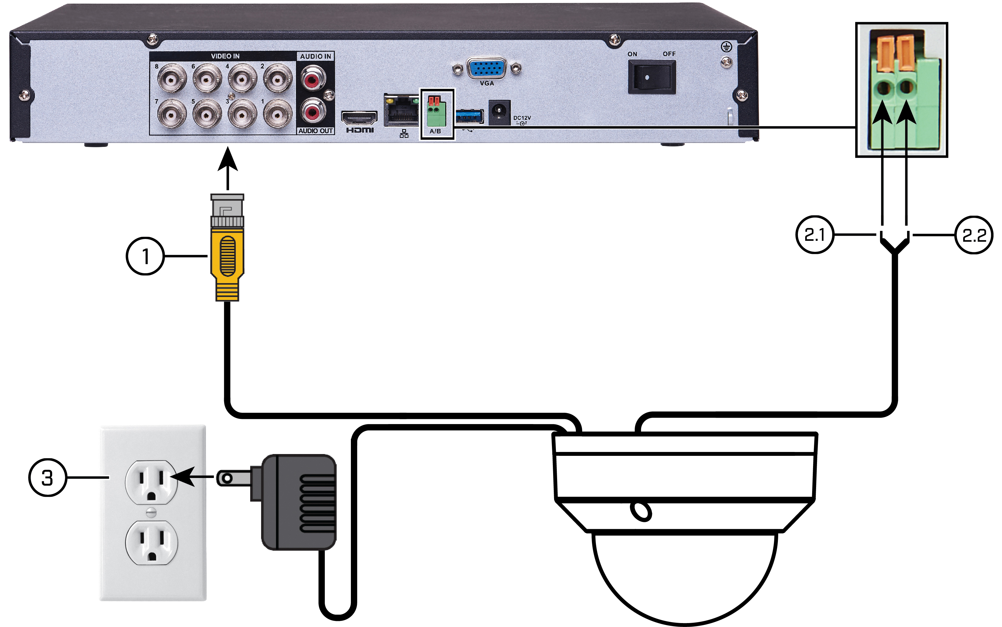
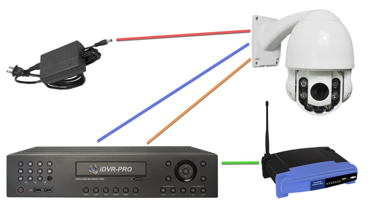
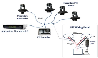
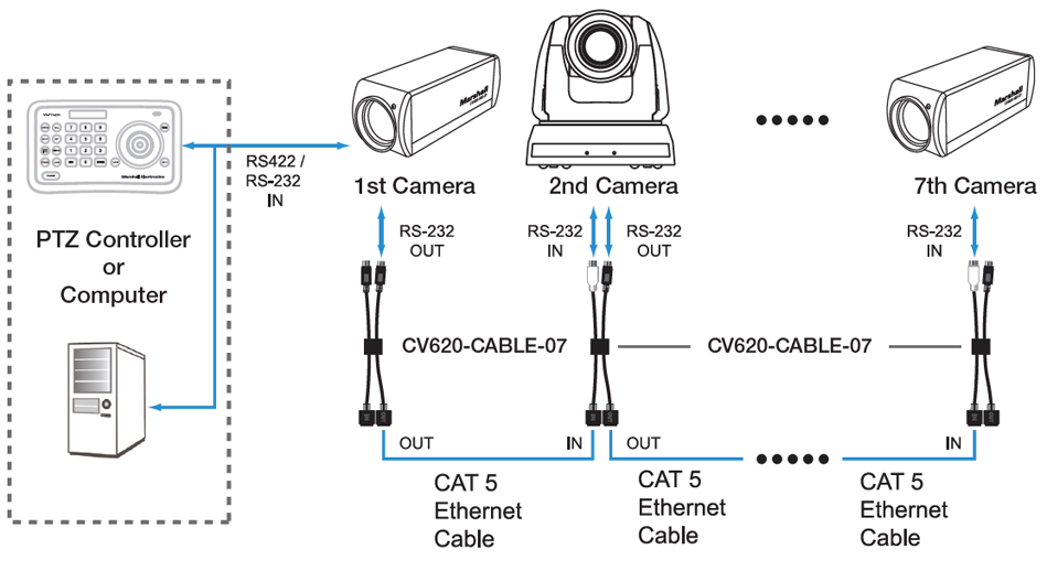
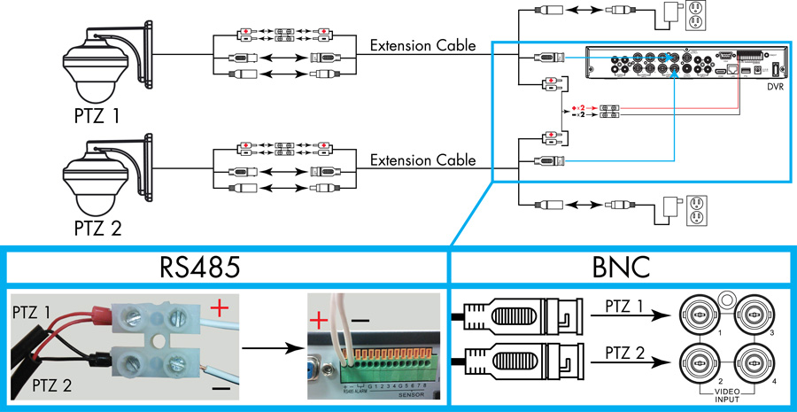
1 input power 12vdc or 24vac 2 control rs 485 3 output video coax cable typically 1vdc p p. The rs configuration on the ptz camera and the control unit must. The following diagram shows an example ptz camera system installation using the ck 983321 ptz camera controller the idvr pro cctv camera dvr and 3 pan tilt zoom cameras. Simple wiring diagram a quick review of a ptz cameras wiring figure 2 concludes there are three 3 pairs of wires to be concerned about. The bnc cables are used for video signal transmission while the rs 485 cables are used to control the camera movement and rotation by connecting it to the joystick ptz controller or dvr system. Addition is that it has an extra wire pair known as the rs communication wires which sends communication signals from your.
A wiring diagram is a streamlined conventional photographic representation of an electric circuit. A wiring diagram is a streamlined standard pictorial depiction of an electrical circuit. Ptz camera system installation. This 182 power cable can be used to for the rs 485 communication between the joystick and cameras.
Gallery of Ptz Controller Wiring Diagram