The first 100 orders over 50 receive a free stubby holder and sticker pack from built not bought. Redarc recommend using midi fuses along with a quality fuse holder to match.

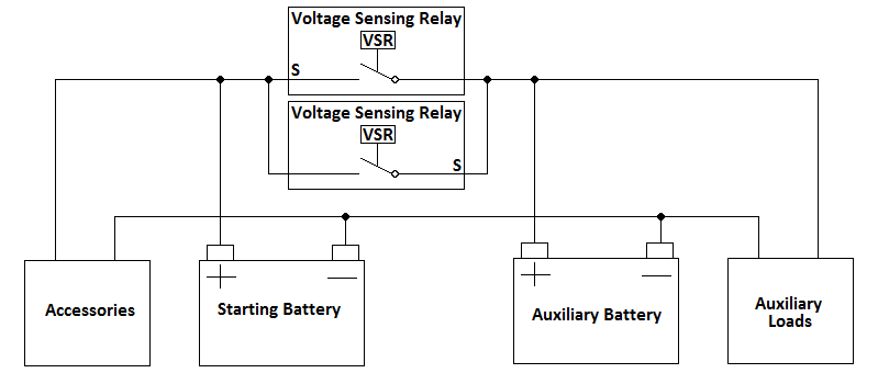
Yl 1341 Battery Wiring Diagram On System With Dual Battery
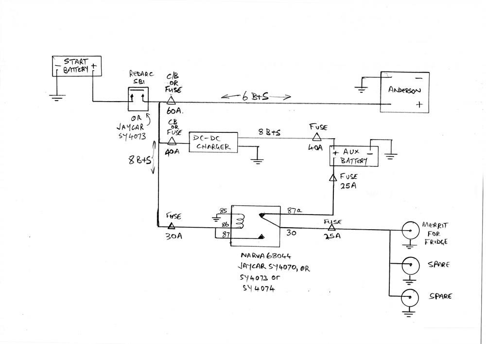
Redarc sbi12 wiring diagram. The below diagram shows how to install a gauge using switches to simulate ignition and dash lights providing a simple way to switch the gauge onoff both withwithout the backlight active. Ensure that all connections are tight and that the provided spring washers are used. The diagram below. When wiring a gauge into a location other than a car dashboard for example in a caravan park and dash lights may not be available. Wiring instructions 9 wire the sbi12 as shown in diagrams mn o. Redarc electronics have a large database of faqs tech tips wiring diagrams and how to guides.
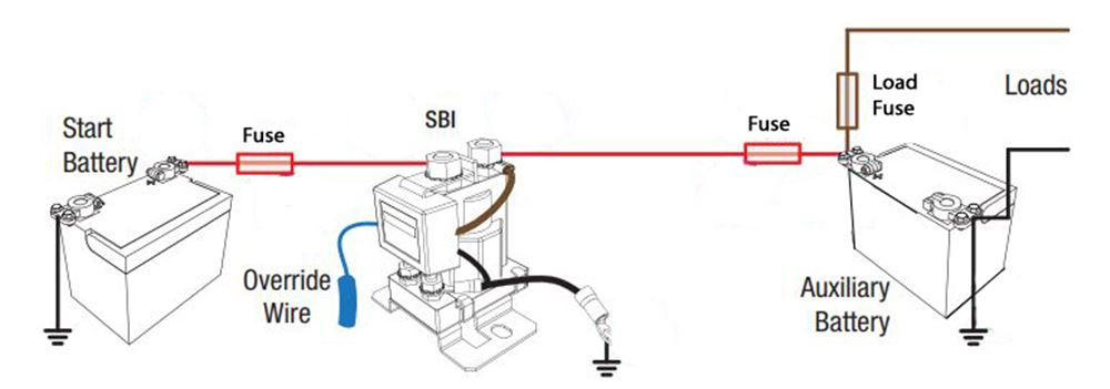
Check them out today. 7 mount the sbi12 7 ensure ground point makes a good electrical connection to the negative terminal of both. Standard wiring diagrams 3 loads load circuit fuse breaker auxiliary battery start battery fuse sbi 3 3 5 4 6 7 1. Sbi12 sbi24 up to 3m 100 amps 19mm² 4bs 60 amps 8mm² 8bs 5 62 nm. 10 reconnect main battery earth nuts bolts and mounting plate not provided. It is used as a solenoid priority system in dual battery systems and provides 12v dc incorporating 100a of continuous ratings.
The redarc smart start sbi12 is a microprocessor controlled battery isolator which protects the start battery from excessive discharge while allowing the auxiliary battery to supply charge to non essential loads.
Gallery of Redarc Sbi12 Wiring Diagram