Determine the wire length required to make the spd phase connections and cut the wires to the appropriate length. A house or building is split into lightning protection zones lpz as a potential surge passes between one zone to another this is where the appropriate spd should be fitted eg.

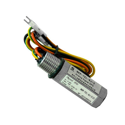
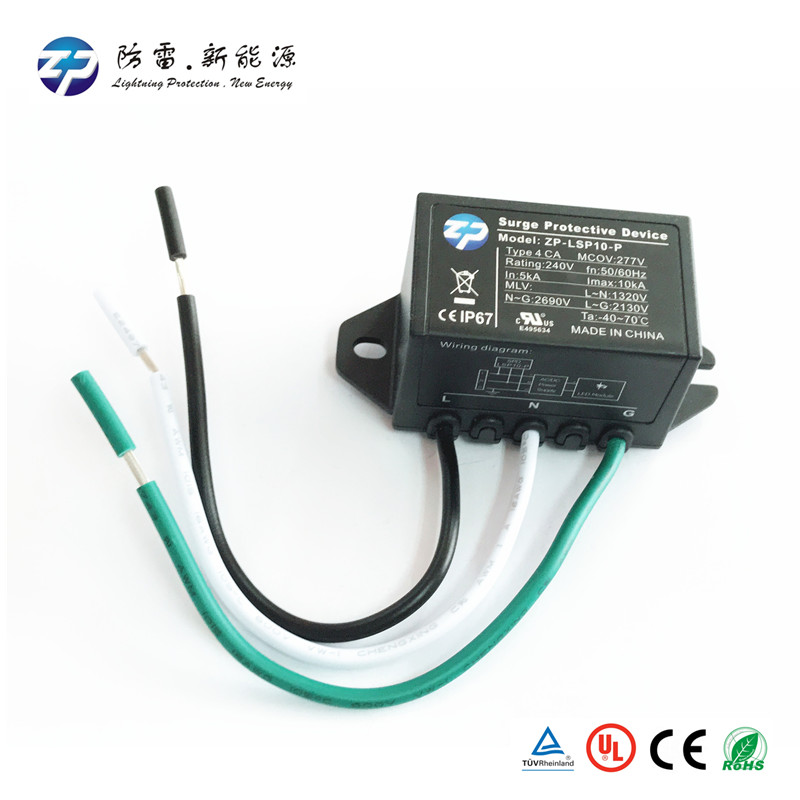
Pv Surge Protection Device Solar Panel Dc Surge Protective Device
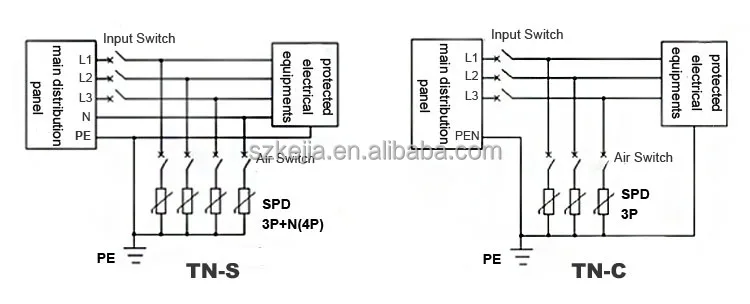
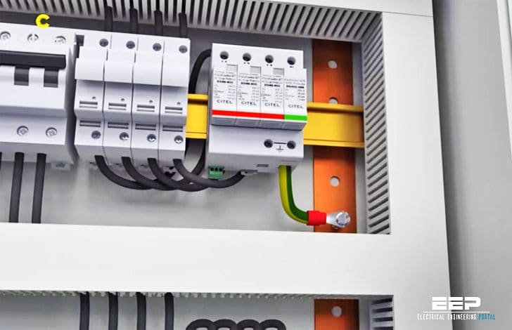
Spd device wiring diagram. The designed performance of the spd and the installation practices used on site. Spd series type 1 and type 2 units do not require over current protection devices fuses or circuit break ers to operate correctly. Warrants to the original customer that the spd products shall be free from defects in materials and workmanship for a period of five 5. Device installation manual the midnite solar surge protective device mnspd is a type 2 device designed for indoor and outdoor applications. Select the correct wiring diagram for the spd you are install ing. See figures 6 7 8 and 9 on page 4.
See figures 8 9 10 and 11 on page 7. Spd connection type 1 ct1 an spd configuration based on connection type 1 ct1 is for tn c s or tn s earthing arrangements as well the tt earthing arrangement where the spd is fitted downstream of the rcd. Midnite solar surge protection device spd midnite solar inc. Select the correct wiring diagram for the spd you are install ing. The spd performance can be. You must refer to this diagram while wiring the spd.
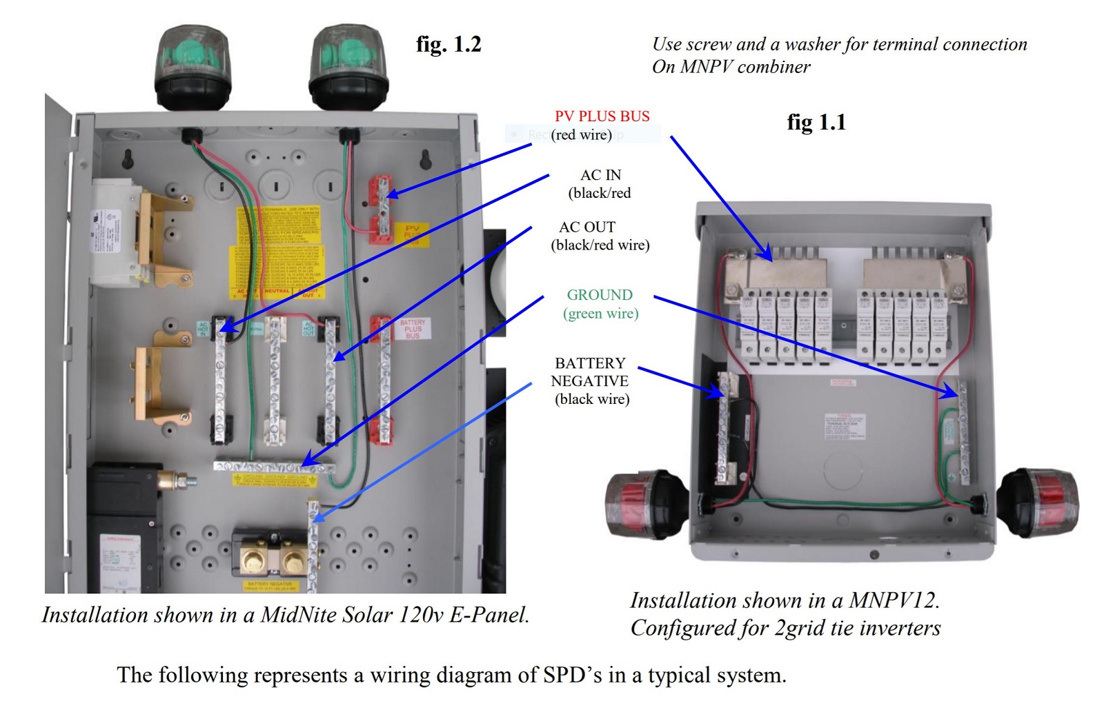
Through the enclosure hole and mount the spd enclosure. Spd can be used with any electric panel. Select the correct wiring diagram for the spd you are install ing. Installation shown with midnite solar e combiner box. Between the outside lpz0a to the inside of a building lpz1 spd. With an overall length of 1m of wiring including the spd fuse connection will have a let through voltage of 1500v.
Spd wires through the enclosure hole and mount the spd enclosure. Spd performance is a function of the connecting lead length. You must refer to this diagram while wiring the spd. In case you are not familiar with surge protective devices operation and types you better read first the basics of surge protective devices. You must refer to this diagram while wiring the spd. Eaton spd series surge protective device for integrated nits 6.
Dimensions for 50 200ka units mounting 880 2235 terminals 874 2220 466 1184. Box after wiring is completed using drywall anchors. Make sure to grommet the hole in the distribution box. The following represents a wiring diagram of spds in a typical system. See figures 9 14. Midnite solar inc.
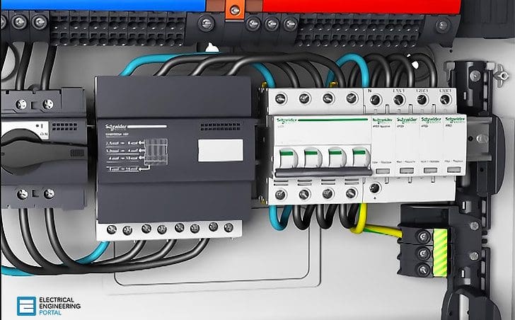
Wiring of the installation and cause damage by considering which device to install. Self inductance of wiring is proportional both to its length and to the logarithm of its thickness. The performance of a surge protection device spd is governed by two main factors. However the installation will be better protected if both devices are installed on 2 different din rails spd underneath the protection the number of lightning strikes that the surge protection device can absorb will decrease with the value of the discharge current from 15 strikes for a current at value in to a single strike at imaxiimp. Bus connection figure 4. Halving the length of connecting wires halves the inductance but the thickness would have to be increased tenfold to achieve the same effect.
Gallery of Spd Device Wiring Diagram