A wiring diagram is a streamlined standard photographic depiction of an electric circuit. Phase converter wiring diagrams.

Wiring Diagrams For Rotary Phase Convertor Electrical
Rotary phase converter wiring diagram. Wellborn collection of rotary phase converter wiring diagram. Ronk roto phase wiring diagram wiring diagram rotary phase converter wiring diagram wiring diagram includes several detailed illustrations that present the relationship of varied things. It shows the elements of the circuit as simplified shapes and the power and also signal connections between the tools. The parts listed were taken from the 1996 grainger catalog 387 for convenience and having a point of common reference. The idler generator motor attaches to one set of holes in the power distribution block. We use the latest proven technology to manufacture industrial grade rotary and static converters.
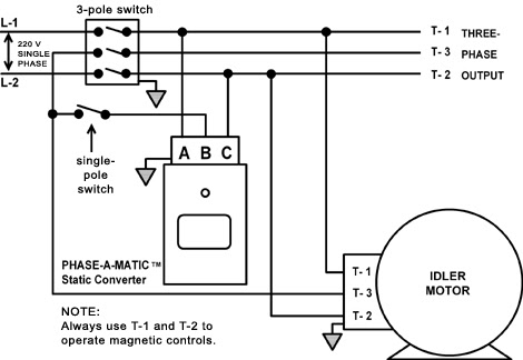
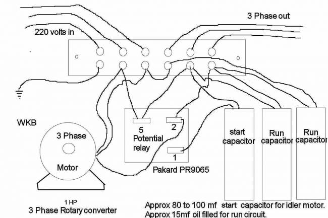
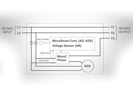
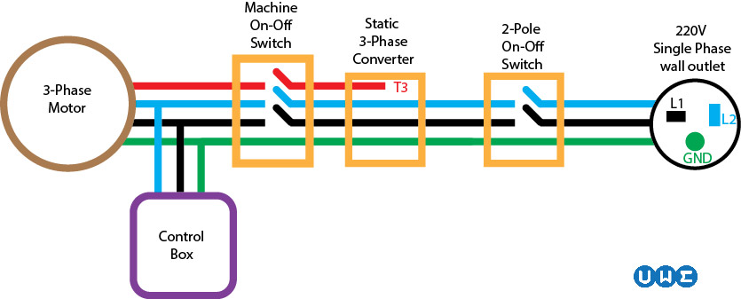
Get it spinning with a rope wrapped around the motor shaft for example to get it going it wont start on its own. Electronicremote blue start leads 2 connect to 240 volt toggle switch three leads indicate power gaurd onoff contactor for electronic start l1 l2 t1 t2 t3. To make a simple rotary phase converter out of a 3 phase motor connect 230 volt single phase power to the t1 and t2 supply terminals or wires of the motor that you are using as a converter. Collection of 3 phase rotary converter wiring diagram. Wiring diagram for loads that american rotary total up to 1 times the maximum converter rated current. It reveals the elements of the circuit as streamlined forms and also the power as well as signal connections between the devices.
Contactor c1 has replaced the drum switch and contactor c2 has replaced the momentary pushbutton for connecting the starting capacitor between l2 and l3. All of our t1 t2 and t3 power distribution blocks are double locks. This document describes typical parts and a schematic for building a single to three phase rotary converter. A wiring diagram is a simplified traditional pictorial representation of an electrical circuit. If you need a different configuration just let us know. 3 phase idler motor l1 l2 t1 t3 t2 230 volt single phase panel american rotary phase converters.
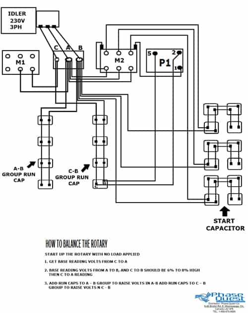
All our pro line 3 phase rotary switch wiring and phase converters include the allen wrenches needed for installation. Wellborn collection of american rotary phase converter wiring diagram. Our three phase converters are ac single to three phase 208v 220v 240v 440v 460v and 480v converters. Above is the field or power wiring diagram. November 27 2018 by larry a. It consists of guidelines and diagrams for various types of wiring methods as well as other items like lights home windows and so forth.
If you look closely you will see all the basic elements from the very simple static phase converter diagram shown earlier. Parts list and notes for making a 10 hp 240v single phase to 240v 3 phase converter. A wiring diagram is a streamlined standard photographic depiction of an electrical circuit. July 7 2018 by larry a. It reveals the elements of the circuit as simplified forms and the power and also signal links in between the gadgets.
Gallery of Rotary Phase Converter Wiring Diagram