It shows the components of the circuit as simplified shapes and also the power and also signal links between the devices. The surge current the spd can handle for 15 strikes 820 s current.

Surge Protection Circuit Principle And Design
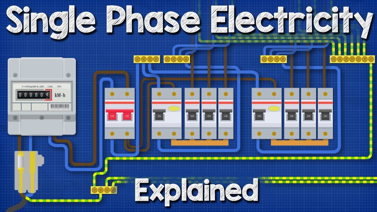
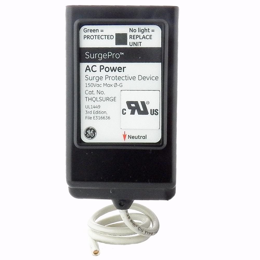
Single phase surge protector wiring diagram. Type 3 protection is required in accordance to 17th edition wiring regulations if cabling distance from a type 1 or 2 spd is greater than 10m or if simply peace. Surge protection 5 wiring lengths connection options duration. Class 1 and class 2 protection for 380vac. Single phase surge protector wiring diagram wiring diagram is a simplified tolerable pictorial representation of an electrical circuit. The maximum surge current between any one phase and neutral that the spd can withstand for a single strike 820 s current. Midnite spds can be used for 3 phase applications.
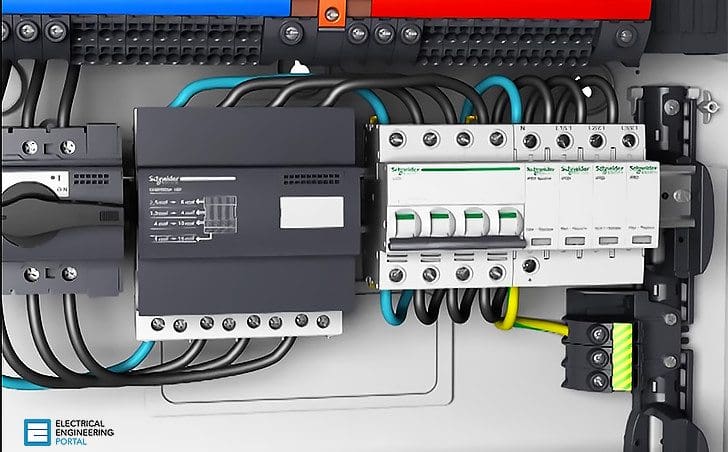
Surge protection devices modular pluggable and high capacity surge protection solutions for commercial and industrial applications. Collection of 3 phase surge protector wiring diagram. A wiring diagram is a simplified traditional photographic representation of an electrical circuit. For the most part a simple two pole device for single phase tt or tns will be enough. Single phase electricity explained wiring diagram energy meter duration. Surge protection for electrical power.
Three spds provide enhanced protection. Here a 25ka at 10. Installation of class 1 and class 2 for 3 phase. Installation of class 1 and class 2 for 3 phase. Surge protection device are. It reveals the components of the circuit as simplified shapes and the power as well as signal connections in between the tools.
As shown in the diagram two or three spds can be used. Voltage protection level u p. It shows the components of the circuit as simplified shapes and the capacity and signal contacts amongst the devices. 50 of this energy is conducted away to earth leaving 100ka potential across the networks 3 phase and neutral. Assortment of surge protector wiring diagram. Wiring diagrams for surge arresters wiring of 1 and of 3 x dehnguard 275 and 1 x dehngap ct.
In tncs systems a single pole unit. L3 l1 l2 gnd l3 l1 gnd l2 two spds provide basic protection. A wiring diagram is a streamlined traditional pictorial depiction of an electrical circuit. In tncs systems a single pole unit may be sufficient as only the live conductor comes to the property that can bring a threat from outside influences affecting that supply. For the most part a simple two pole device for single phase tt or tns will be enough. See the diagram to the right from iec 63205 1 standard which displays the.
To provide lightning and surge protection. Installation of class 1 and class 2 single phase. If greater than 10m then type 3 surge protection should be fitted.
Gallery of Single Phase Surge Protector Wiring Diagram