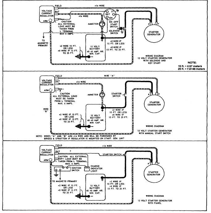
A wiring diagram is a streamlined conventional pictorial representation of an electrical circuit. Variety of starter solenoid wiring diagram chevy.

3 Typical Car Starting System Diagram T Amp X
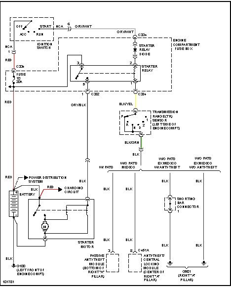
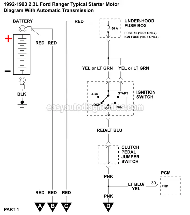
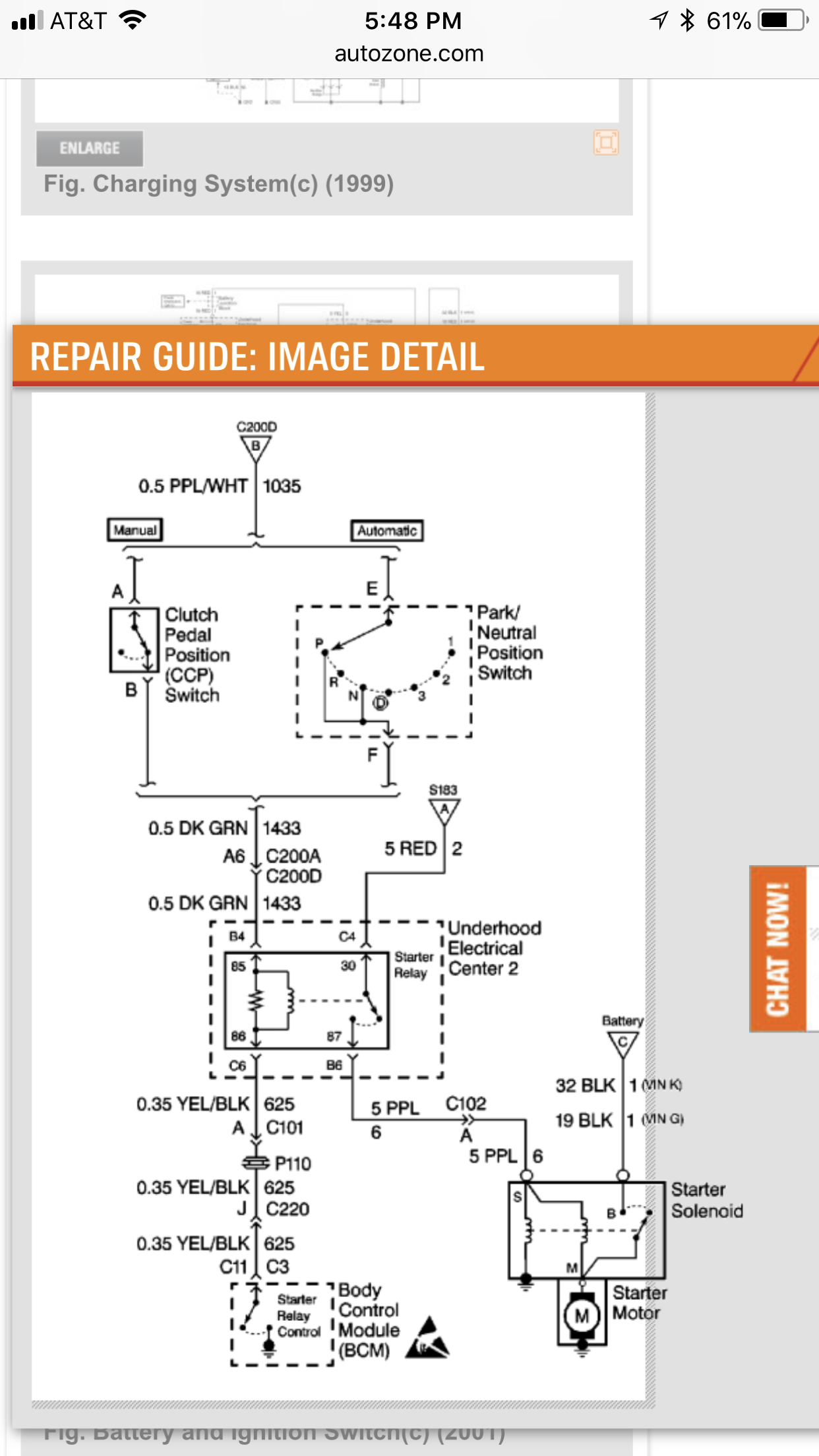
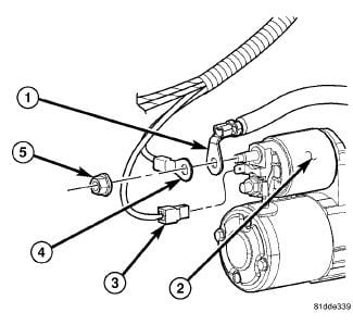
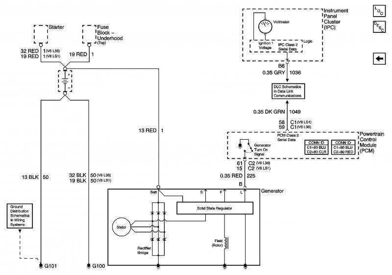
Starter wiring diagram. 3 typical car starting system diagram 1ignition switch usually the ignition switch connects with a key or a button and inside of it has the regular wire. Gm starter solenoid wiring diagram gm starter solenoid wiring diagram every electrical arrangement is made up of various unique pieces. A typical starter solenoid has one small connector for the starter control wire the white connector in the photo and two large terminals. Once the principles of the starting system can be understood then any variations of the wiring can be easily understood. It shows the parts of the circuit as simplified shapes and also the power and also signal connections between the gadgets. The starter solenoid works as a powerful electric relay.
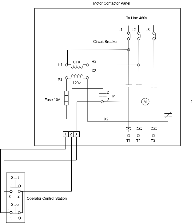
It uses two contactors two auxiliary contact blocks an overload relay a mechanical interlock two normally open start pushbuttons a normally closed stop pushbutton and a power supply with a fuse. Learn to navigate this systems wiring circuitry and diagram using current flow analysis relay and module operation and neutral switch actuation such as circuit completion. Line 1 l1 t1 motor 1 l1 hot 240v or neutral 120v line 2 l2 t2 l3 t3 motor 2 l2 hot 120v or 240v manual starter. This is a picture of the basic principles of any starting system. If not the arrangement will not function as it should be. Merely ignore the control wiring in red 3ph starter3ph motorreversible.
See how the anti. 2starter solenoid the starter solenoid is the main part of the control starter circuit including the with relay type. The basis principles are the battery. Each component should be set and connected with other parts in particular way. One for the positive battery cable and the other for the thick wire that powers the starter motor itself see the diagram below. At the same time the.
Collection of 4 pole starter solenoid wiring diagram. In the tractor starter wiring diagram the circuit starts with the battery at the left of the. This diagram is for 3 phase reversing motor control with 24 vdc control voltage. When activated through the control terminal the solenoid closes the hi current electric circuit and sends the battery power to the starter motor. It reveals the elements of the circuit as streamlined shapes and the power and signal links between the gadgets. A wiring diagram is a simplified traditional photographic representation of an electric circuit.
Gallery of Starter Wiring Diagram