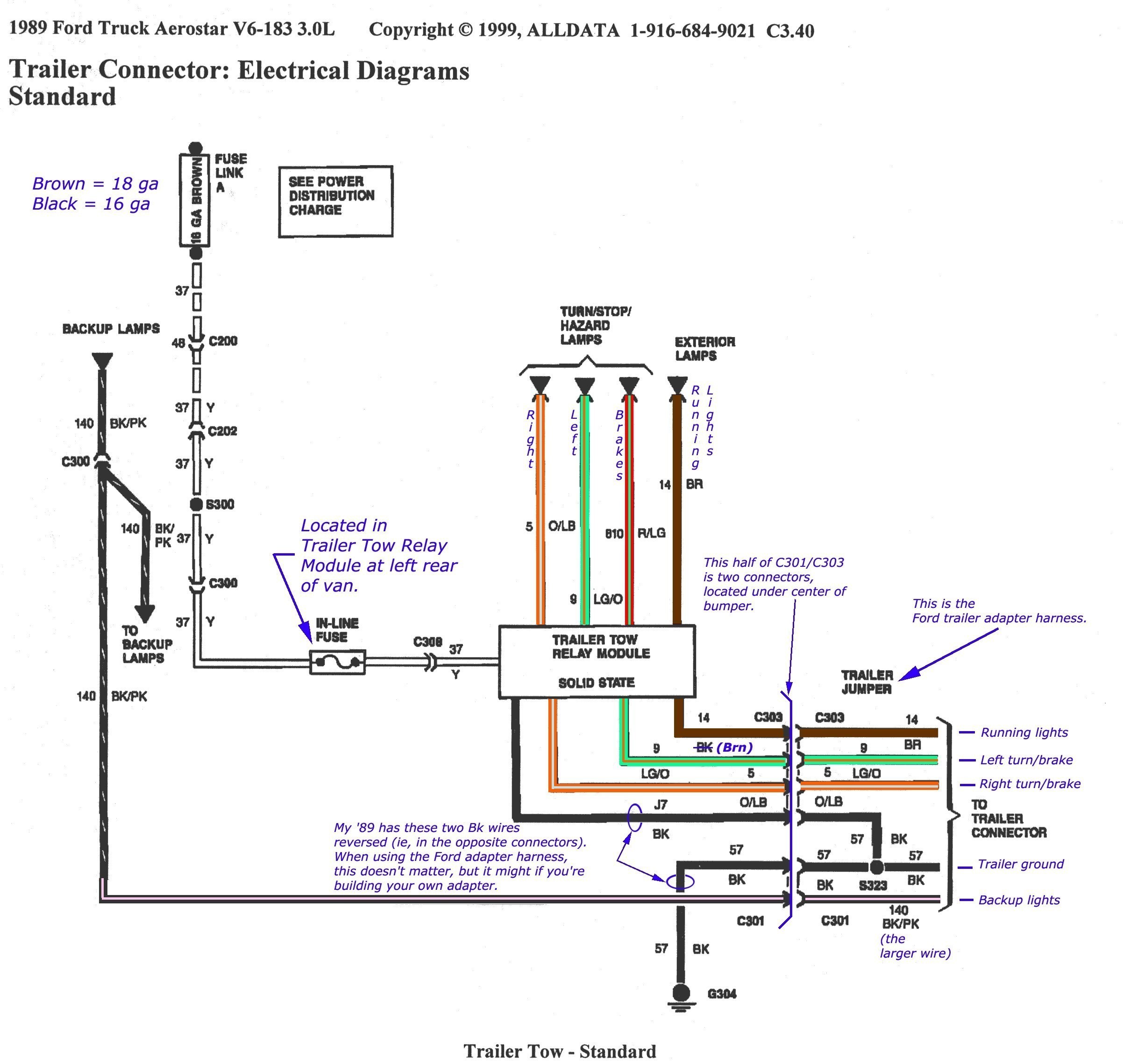
See point b on the wiring diagram. It shows the components of the circuit as streamlined shapes and the power and also signal connections in between the devices.

Vk 8343 Trailer Breakaway Kit Wiring Diagram Download Diagram
Trailer breakaway switch wiring diagram. A wiring diagram is a simplified conventional pictorial depiction of an electric circuit. You may have to cut into the trailer wirings sheathing to find the wire. This trailer breakaway wiring diagram version is more appropriate for sophisticated trailers and rvs. A wiring diagram is a simplified conventional photographic depiction of an electric circuit. I attached a diagram showing how a breakaway switch like part 420000 would be wired to a trailer mounted battery like the one on your loudo dump trailer. January 23 2020 by larry a.
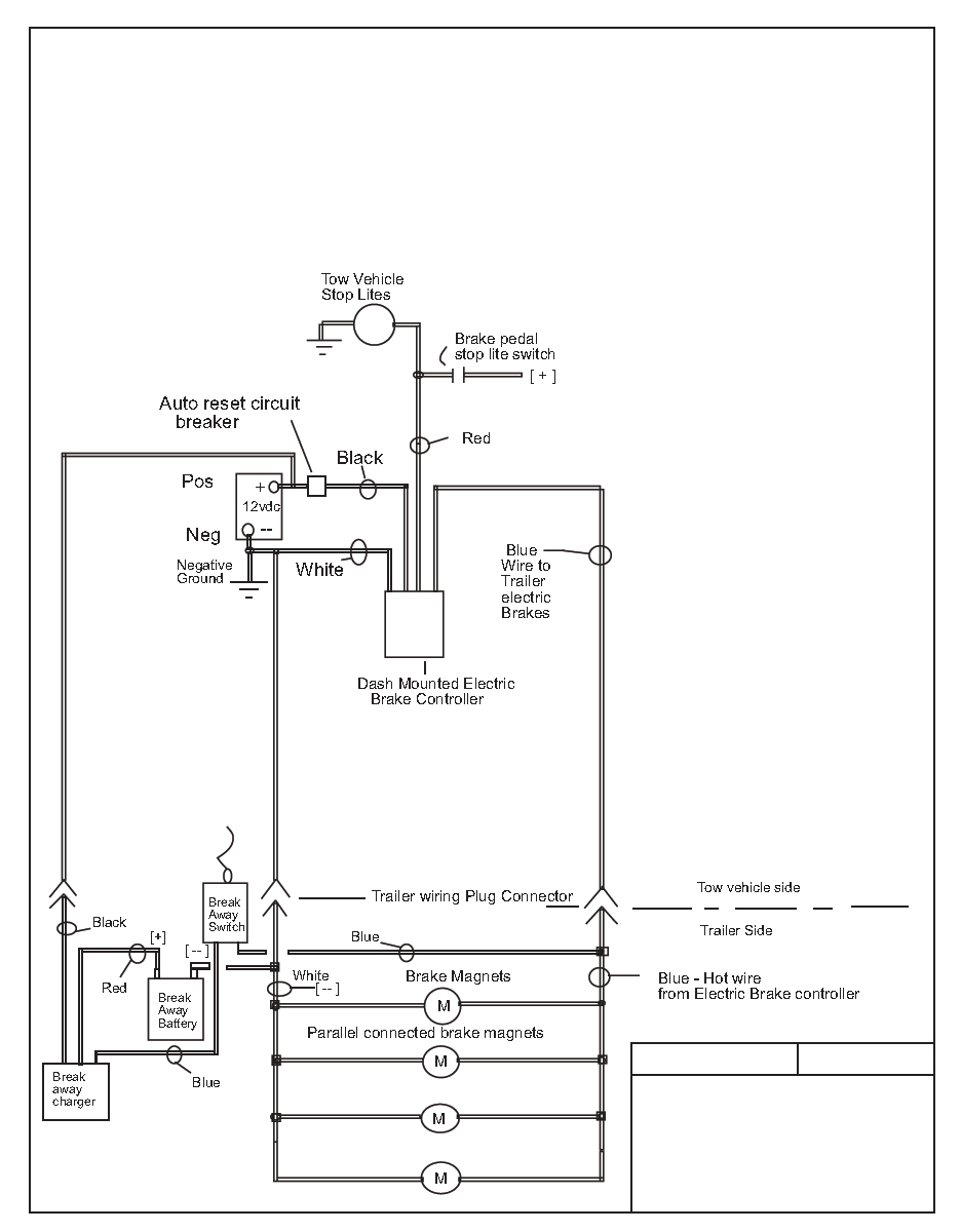
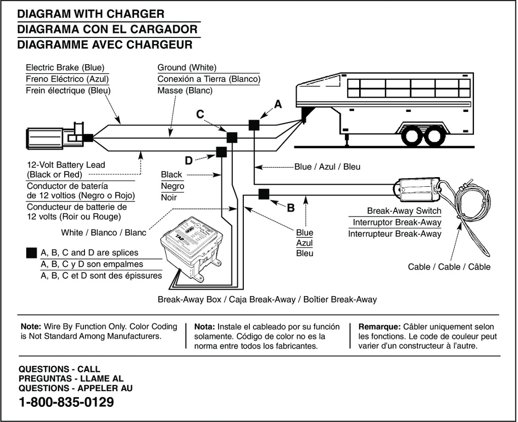
Splice one blue wire of the break away switch to the electric brake wire coming from the trailer side connector a see diagram on next page. If that happens a safety line will pull the plunger. 2 break away switch safety chain pocket bumper clevis figi cable pin break away switch fig. 3 cable installation 1. This connection will send power to the breakaway switch. Connect the breakaway switchs other lead to the blue wire with a scotchlok connector.
Both wires on the breakaway switch are interchangeable. Splice one blue wire of the break away switch to the electric brake wire coming from the trailer side connector a see diagram on next page. Wellborn variety of trailer breakaway switch wiring diagram. The breakaway switch is there in case the fifth wheel trailer and the truck becomes separated during towing. This 3 wire trailer breakaway switch wiring diagram version is more acceptable for sophisticated trailers and rvs. Connect the second wire coming out of the switch to the brake wire blue coming out of the battery box.
Connect other blue wire of break away switch to the blue wire labeled brake from the break away box b. White pin for the ground. See point a on the wiring diagram. If necessary extend the wire from the trailer breakaway switch with 14 gauge automotive primary wire and solderless connectors. With this type of setup you would not want to pull the breakaway switch with the trailer connected to the vehicle to avoid a short circuit situation which could damage your brake controller. It reveals the components of the circuit as streamlined shapes and the power and signal connections between the tools.
Here is the diagram for 7 pin connector. It can transfer power better hence the connector is recommended for higher level electric in the car. Variety of trailer breakaway wiring schematic. White pin for the ground. Blue wires are interchangeable on the break away switch 3. It may transfer power better hence the connector is suggested for higher level electric in the car.
Here is the diagram for 7 pin connector. I explain the wiring and test it.
Gallery of Trailer Breakaway Switch Wiring Diagram