It offers excellent non contact range detection with high accuracy and stable readings in an easy to use package. Were here in the main workspace window.
Ultrasonic Sensor Arduino Interfacing The Engineering Projects
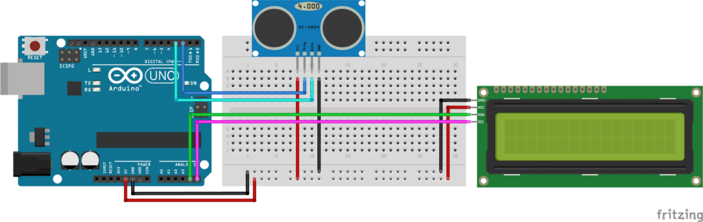
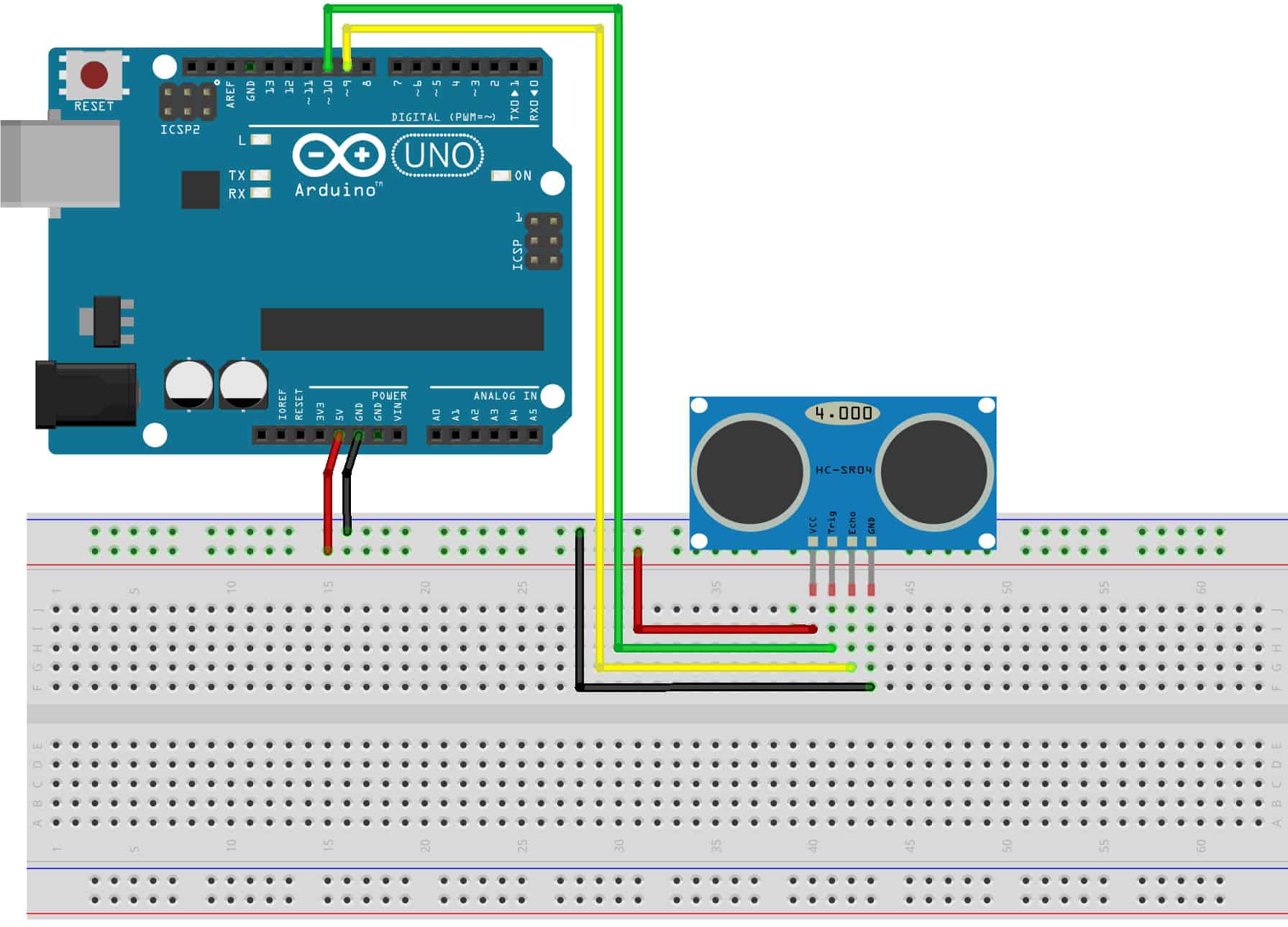
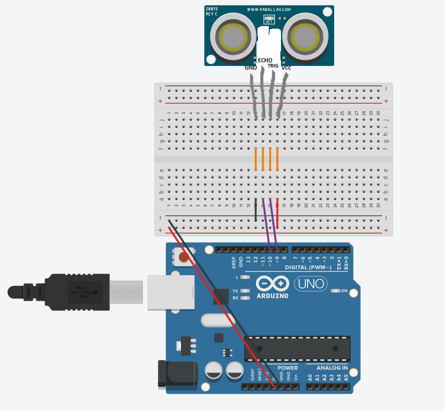
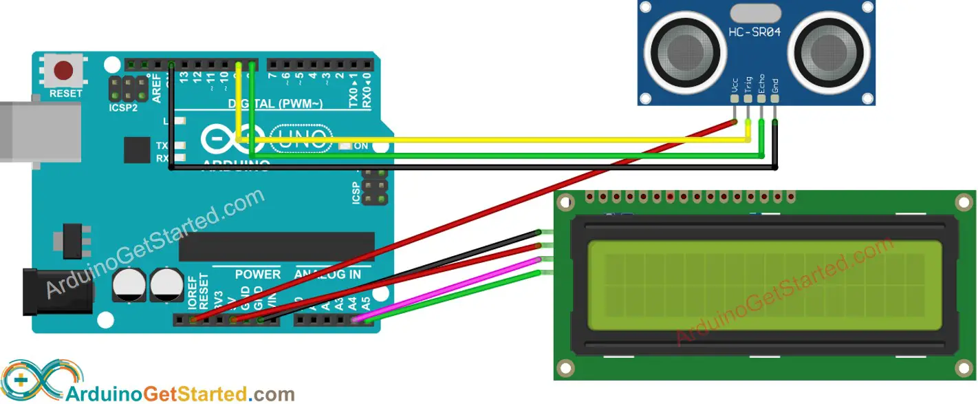
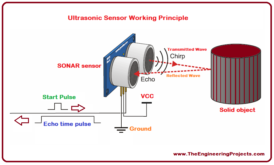
Ultrasonic sensor wiring diagram. In this session well look at the basic sensor wiring for both six wire and nine wire sensors. Well click on the workspace icon on the toolbar and im going to load the default settings for a tspc 30s1 toughsonic 14 sensor. Hc sr04 ultrasonic sensor working. This sensor is a very popular sensor used in many applications where measuring distance or sensing objects are required. You can place the ultrasonic sensor as shown on the breadboard and with jumper wires complete the wiring to the arduino. Wiring esp8266 nodemcu with hcsr04 ultrasonic sensor in this illustration we will going to wire the esp8266 12e nodemcu with ultrasonic raging sensor hcsr04.
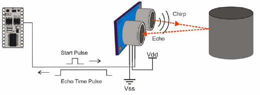
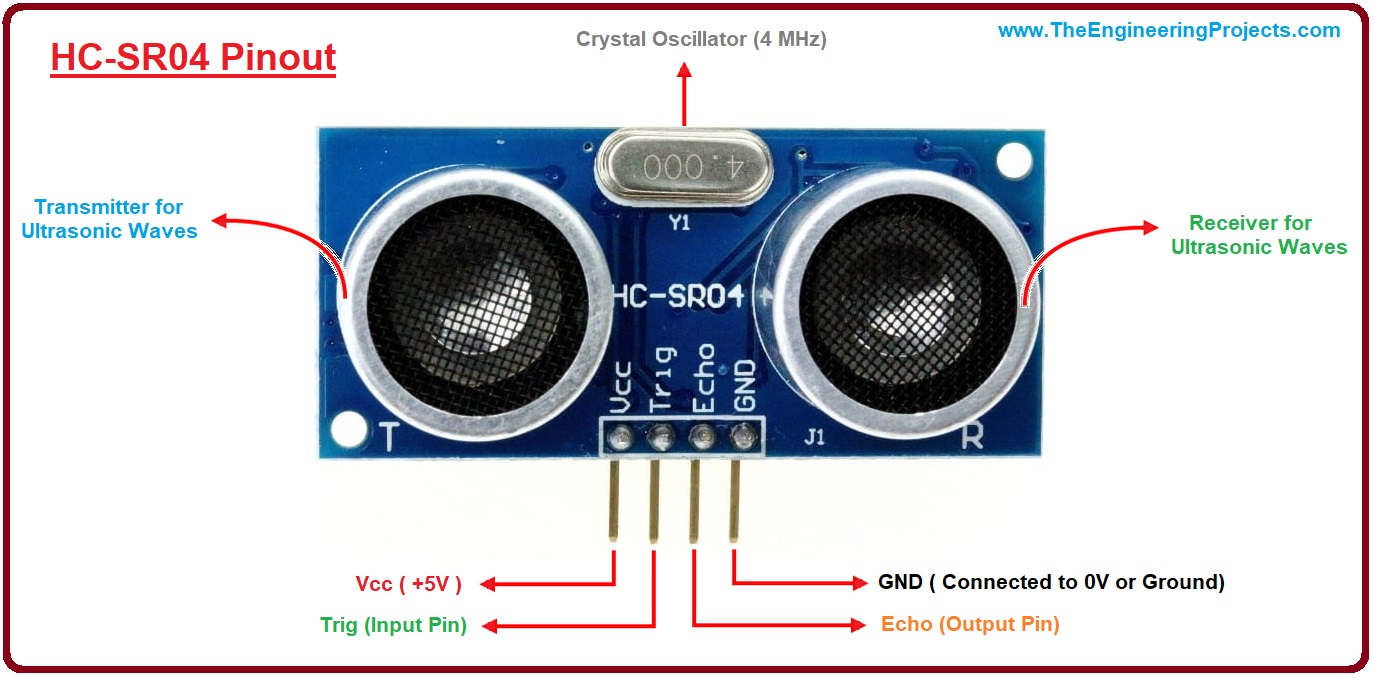
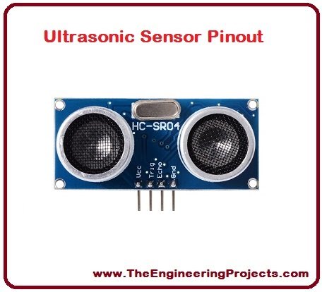
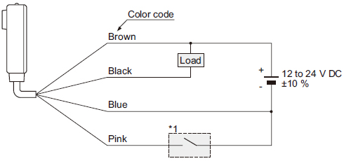
As you can see the illustration below the sensor trigger pin is connected to d1 which is pin 5 in arduino board and the echo is connected to d2 which is pin 4 in arduino board. Ultrasonic sensors exhibit excellence in suppressing background interference. If you are using a 4 pin ultrasonic sensor the normally closed pin nc is wired to ground. As shown above the hc sr04 ultrasonic us sensor is a 4 pin module whose pin names are vcc trigger echo and ground respectively. The ultrasonic sensor sends the ultrasonic pulse at 40 khz which travels through the air. These transducers are better than the infrared sensors because these ultrasonic transducersensors are not affected by the smoke black materials etc.
The electrical wiring diagram for an actual ultrasonic sensor to an arduino. The hc sr04 ultrasonic sensor uses sonar to determine distance to an object like bats do. We provide a schematic diagram on how to wire the ultrasonic sensor and an example sketch to use with the arduino. Youll notice on the toolbar several of the icons are in color and.
Gallery of Ultrasonic Sensor Wiring Diagram