Solax eps box solax eps box model eps box grid max. Refer to table 2.
.jpg)
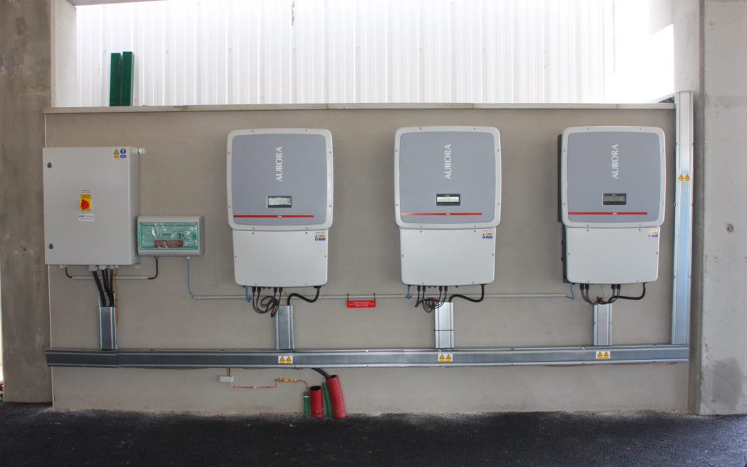
Solax Retro Fit Self Consumption Optimization Kit
Solax eps wiring diagram. Eps wiring diagram for australianew zealand for other countries eps connection steps. Make wireeps cable size. Neutral line of alternative supply must not be isolated or switched. Neutral line of alternative supply can be isolated or switched. For sk tl series the fuse and battery are not used. It is compatible with x hybrid e series inverter.
Eps wiring diagram the below diagram are for reference based on different local wiring rules please follow the local rules for the externel wiring to choose suitable wiring mode. In this video we show you how to manually reset a solax box solar panel system after it being overloaded by a heavy load during eps or emergency power supply or load shedding in cape town. Make sure that existing wiring is in good condition and that wire is not undersized. Solax meter battery e bar ma in swtch rcd pv1 pv1 pv2 pv2 pe solax x3 hybrid inverter loads l2 l1 l1l2l3n l3 n eps loads l1l2l3 n rcd n bar the cable is. Ac input current a 63 rated ac voltage v 230 rated ac frequency hz 5060 eps rated eps current a 17 rated eps voltage v 230 rated eps frequency hz 5060 load rated load output current a grid mode 63 rated load output current a eps mode 17 rated grid voltage v 230. Configured with eps box customers just need to connect 6 wires between inverter and eps box.
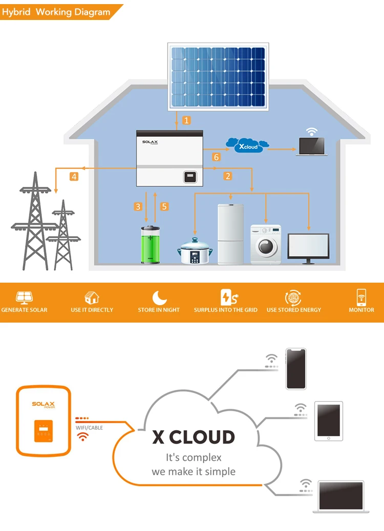
Eps box integrates two contactors which provides simple connection for users. It can simplify the operation and. Connect pe wire into n port at right. X hybrid e version with eps can supply the energy from battery and pv generator when the grid is lost. Use only attachments recommended or sold by solax.
Gallery of Solax Eps Wiring Diagram