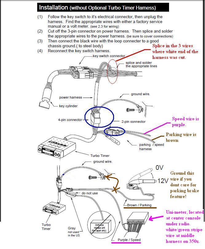
925st 1 theseturbo timers simply plug in to the existing connectors which link the ignition switch to the vehicle wiring. Refer to the wiring table below and the wiring diagram in this manual to connect the controller.
Turbo Timer X Electronics Product Hks
Turbo timer wiring diagram. This will provide protection from heat and abrasion and any other excess damage that may occur with extended vehicle operation. October 13 1998 changes since 13 added basic wiring diagram changes since 12 added section on timer operation added to testing section changes since 11 found out the the version of the turbo timer i have is. Oct 16 blitz turbo timer wiring diagram rhmaerkangorg also dodge stealth wiring diagram how many y s are in a vacuum line rhaskyourpriceme and apexi turbo timer manual. Get mad mcm gear gear here including stickers magazines dvds clothing mods and music at. Nissan r32 gtr built 26 litre 494kw 670hp at the wheels with 34psi of boost pressure. Installing an hks turbo timer installing an hks turbo timer iv vehicle.
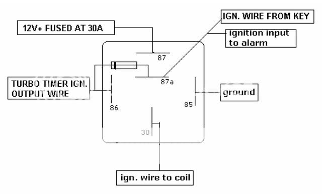
It shows the components of the circuit as simplified shapes and the gift and signal links in the middle of the devices. Harness and place the optional turbo timer harness in line with the key switch harness. Apexi turbo timer wiring diagram apexi style turbo timer for universal car auto with original box and apexi turbo timer wiring diagram wiring diagram is a simplified usual pictorial representation of an electrical circuit. Hks turbo timer wiring diagram as well c er battery hook up rh abetter pw zx apexi manual hks turbo timer contents turbo timer wiring diagram 33 great 55 elegant 3. 1991 toyota mr2 turbo canadian model author. Not for kenworth applications.
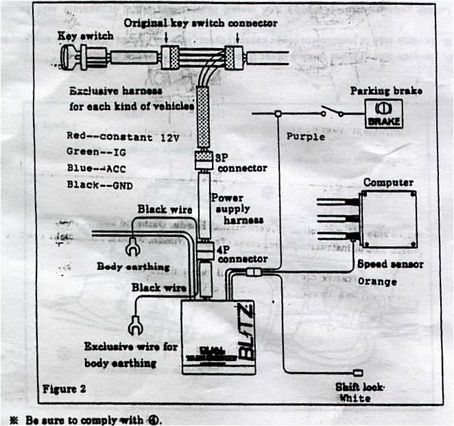
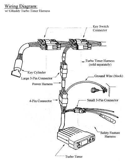
Not for electronic engine applications. 3 then connect the black wire with the loop connecter to a good chassis ground to steel body 2. 1 connect the brown wire from the turbo timer to the supplied brown rpm signal lead wire. Tcheseonnectors will be located in one of the following locations. 2 connect the supplied power harness in between the 3 pin connector of the optional harness and the 4 pin connector of the turbo timer. Connect the turbo timer green wire to the vehicle parking brake wire.
Connecting the turbo timer wire in style timers 925st 1. Boosted by aeroflow 666282 t3 flange. The backon of the ignition switch itself. Ensure good earthing of the timer black wire. If this feature is not required connect the green wire to negative. In this episode the boys teach you how to install a turbo timer.
It is recommended that the wiring is installed alongside the oem wiring ensuring that it is secured at regular intervals. 2 refer to the corresponding vehicle list to find the correct ecu diagram. Connecting the turbo timer plug in style timers connecting the turbo timer wire in style timers.
Gallery of Turbo Timer Wiring Diagram